
Electrical arrangement of shading device

a shading device and electric arrangement technology, applied in the field of shading devices, can solve the problems of inability to guarantee the existence of electrical power sources, the problem of power sources becoming more serious, so as to reduce the manufacturing cost of shading devices, economic and efficient, and simple electrical

Inactive Publication Date: 2010-12-23
MA SRL
View PDF11 Cites 8 Cited by
  • Summary
  • Abstract
  • Description
  • Claims
  • Application Information

AI Technical Summary

Benefits of technology

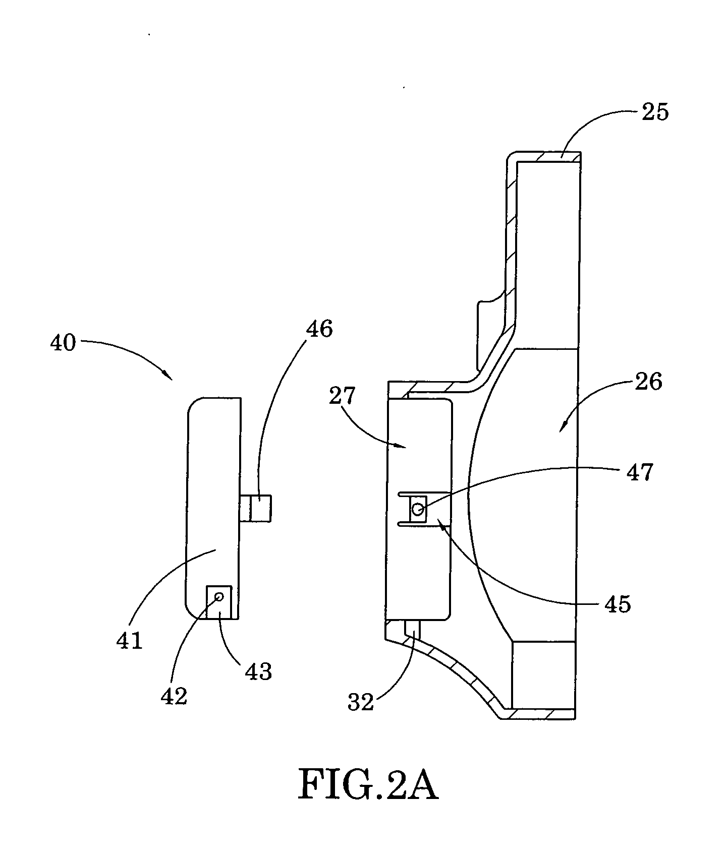
[0010]Another object of the present invention is to provide a rechargeable battery arrangement for a shading device, wherein the rechargeable battery arrangement is detachably mounted on an operation housing of the shading device, wherein the battery unit can be conveniently detached and recharged by using an external electrical power source.
[0011]Another object of the present invention is to provide a rechargeable battery arrangement for a shading device, wherein the battery unit of the rechargeable battery arrangement can be disengaged from the supporting shaft by pressing a releasing button located on the operation housing. Therefore, the user is able to easily and quickly operate the attaching / detaching operation of the rechargeable battery arrangement.
[0015]Another object of the present invention is to provide a rechargeable battery arrangement for a shading device, which does not require altering the original structural configuration of the shading device so as to reduce the manufacturing cost of the shading device incorporating with the rechargeable battery arrangement.
[0016]Another object of the present invention is to provide a rechargeable battery arrangement for a shading device, wherein no expensive or mechanical structure is required to employ in the present invention in order to achieve the above mentioned objects. Therefore, the present invention successfully provides an economic and efficient solution not only for providing a simple electrical configuration of the outdoor umbrella but also for enhancing the practice use of the shading device.

Problems solved by technology

While enjoying the shading area during the daytime, people may need some entertainment equipment such as stereo or other electronic devices to listen to the music, watch videos or play video games, and the power source is a problem under the circumstances.
Furthermore, in the nighttime, a lighting fixture is necessary for outdoor illumination and the power source becomes a more serious problem than that during the daytime.
In other words, the outdoor umbrellas, as the name implies, are designed for use in outdoors, existence of an electrical power source cannot be guaranteed.
Also, it is inconvenient and impractical for the user to extend an electrical cord from the dwelling to the patio or garden area, much less the campground or beach area.
Even though the solar energy arrangement is convenient and environmentally friendly, it may not provide sufficient energy during the nighttime without sunlight or when there is not enough sunlight, and the lighting fixture or electronic devices may not under their best working condition without sufficient electrical energy.
Also, the solar energy arrangement may somewhat decrease the aesthetic value of the outdoor umbrella.

Method used


Image

  • Electrical arrangement of shading device
  • Electrical arrangement of shading device
  • Electrical arrangement of shading device

Examples


Embodiment Construction

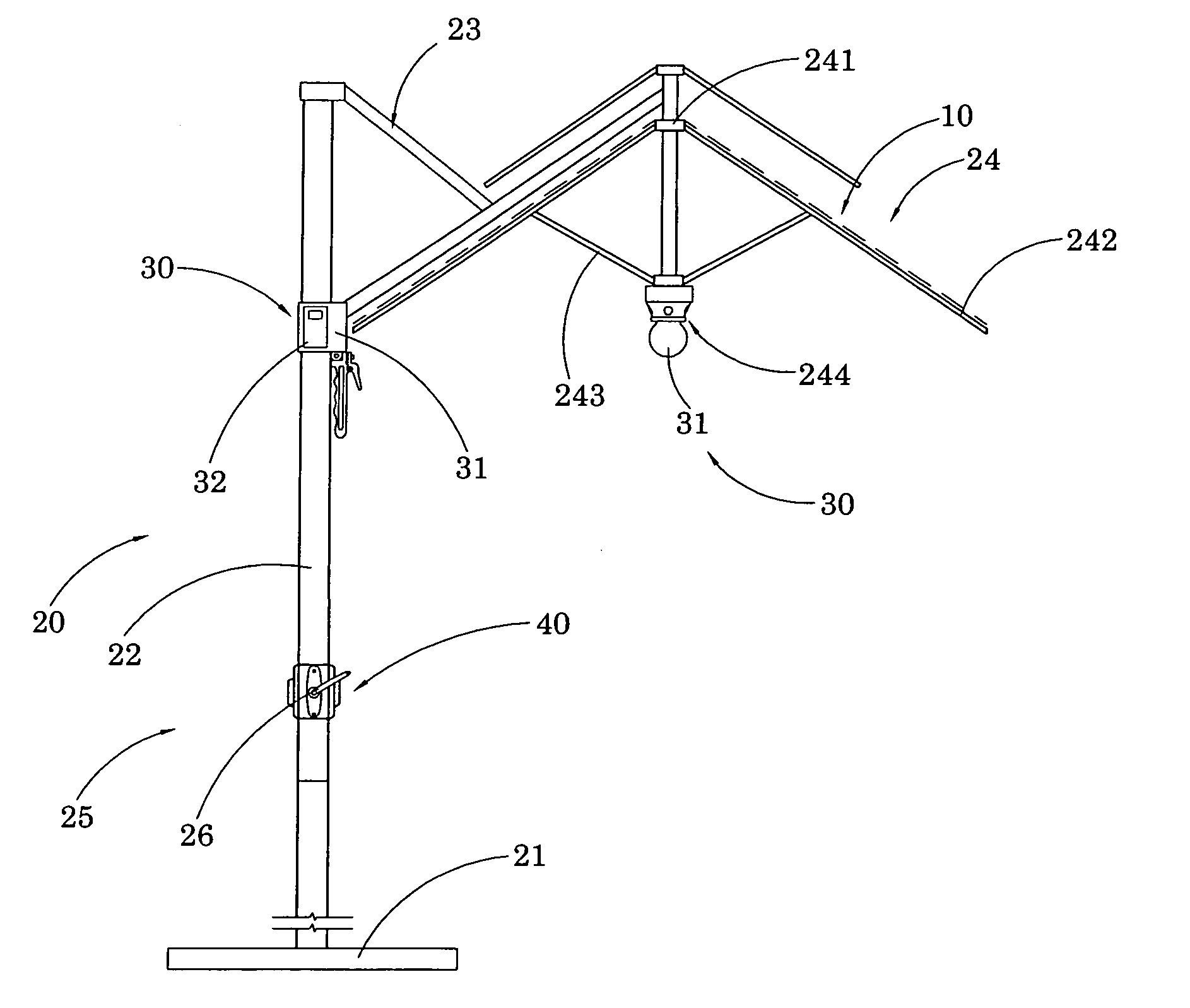
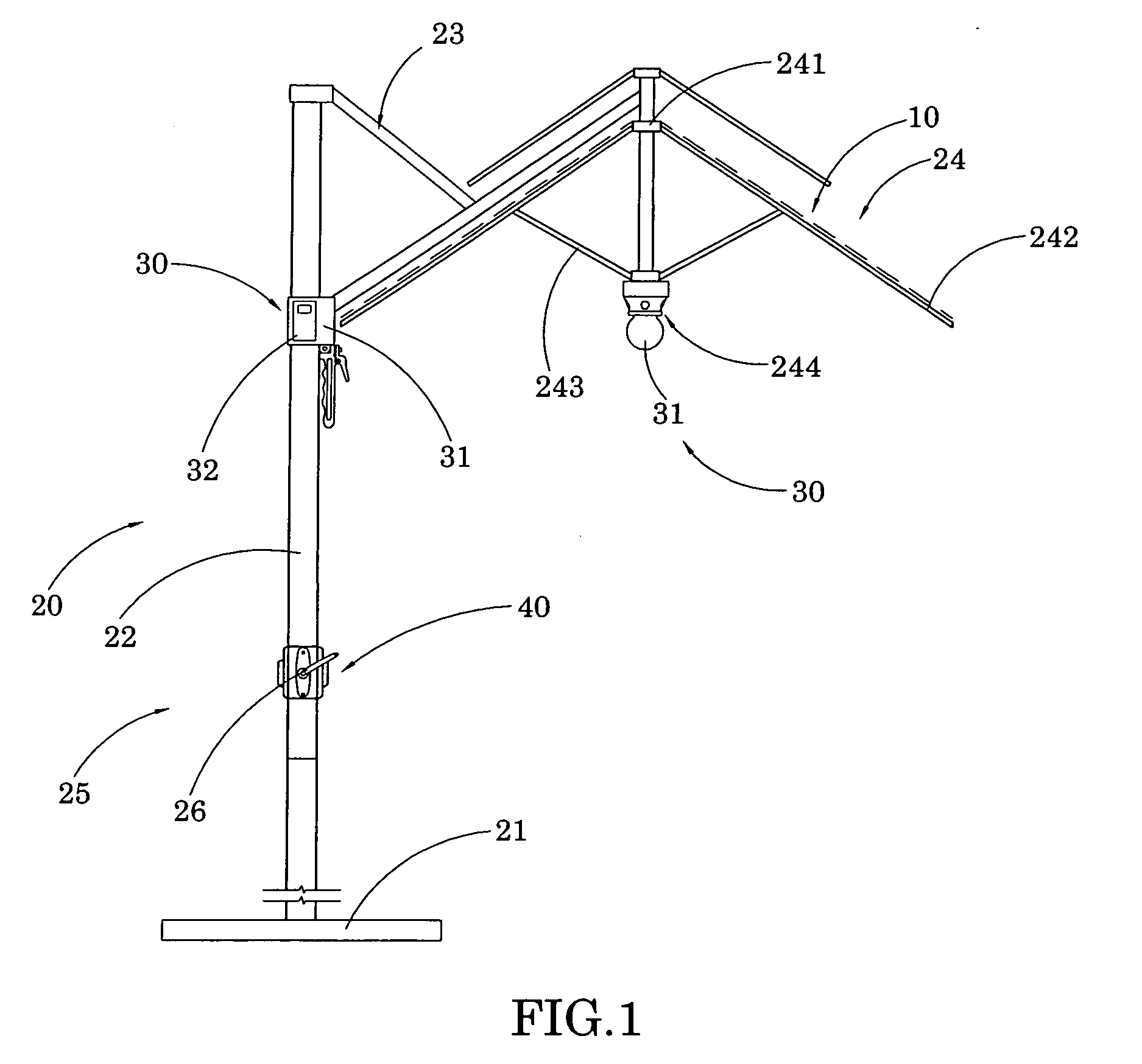
[0033]Referring to FIG. 1 of the drawings, a shading device according to a first preferred embodiment of the present invention is illustrated. According to the first preferred embodiment, the shading device comprises an awning supported by an awning supporting structure to provide a shading area under the awning. For example, the shading device, which is embodied as an outdoor umbrella, comprises an umbrella awning 10, an umbrella frame 20 which supports the umbrella awning 10, an electrical arrangement 30 supported at the umbrella frame 20, and a rechargeable power source 40 which provides electrical power to the electrical arrangement 30 to be operated without using an electrical cord.

[0034]The umbrella frame 20 comprises a base 21, a supporting shaft 22 vertically mounted on top of the base 21, a connecting arm 23 sidewardly extended from a top portion of the supporting shaft 22 in a pivotally movable manner, and a foldable awning frame 24 suspendedly supported by the supporting ...


PUM


Abstract

An electrical arrangement includes a releasable unit and a locking arrangement which contains a releasable locker to detachably couple the releasable unit with the shading device and to ensure contact with the electrical arrangement so as to electrically connect the releasable unit of the electrical arrangement.

Description

CROSS REFERENCE OF RELATED APPLICATION[0001]This is a Continuation application that claims the benefit of priority under 35 U.S.C. §119 to a non-provisional application Ser. No. 11 / 985,415, filed Nov. 14, 2007.BACKGROUND OF THE PRESENT INVENTION[0002]1. Field of Invention[0003]The present invention relates to a shading device, and more particularly to a shading device, such as an outdoor umbrella, with rechargeable battery arrangement which is detachably mounted to the structure of the shading device to electrically connect with an electrical arrangement thereof so as to provide electrical energy to electrical arrangement, such as an audio / video system or an illumination system.[0004]2. Description of Related Arts[0005]Foldable outdoor umbrellas are usually set up in outdoor area, such as the patio area, garden area, campground or beach area, to provide a shade for the users to avoid excessive exposure of vigorous sunlight. A conventional outdoor umbrella generally comprises a stand...

Claims


Application Information

Patent Timeline
Patent Type & Authority Applications(United States)
IPC IPC(8): A45B25/00
CPCA45B3/00Y10S135/91
Inventor LI, WANDA YING
Owner MA SRL
Learn More