Solar Cell With Structured Gridline Endpoints Vertices

Inactive Publication Date: 2010-12-23
SOLARWORLD IND GMBH
View PDF59 Cites 8 Cited by
  • Summary
  • Abstract
  • Description
  • Claims
  • Application Information

AI Technical Summary

Benefits of technology

[0015]In accordance with yet another aspect of the present invention, a micro-extrusion system further includes a busbar printing apparatus positioned to print busbars onto the substrate immediately before the micro-extrusion printhead is utilized to form the high aspect ratio gridlines described above. Th

Problems solved by technology

These very wide and thin dimensions (low aspect ratio) create a challenge for conventional extrusion printing.
Furthermore, die-swell, the tendency for the ink bead to expand after it exits the nozzle, causes further thickening of the wet printed line.
In particular, FIG. 20 shows a problem commonly arising in the extrusion printing of the front metallization of H-pattern solar cell 30, where weak

Method used


Image

  • Solar Cell With Structured Gridline Endpoints Vertices
  • Solar Cell With Structured Gridline Endpoints Vertices
  • Solar Cell With Structured Gridline Endpoints Vertices

Examples


Example

DETAILED DESCRIPTION OF THE DRAWINGS

[0038]The present invention relates to an improvement in micro-extrusion systems. The following description is presented to enable one of ordinary skill in the art to make and use the invention as provided in the context of a particular application and its requirements. As used herein, directional terms such as “upper”, “top”, “lower”, “bottom”, “front”, “rear”, and “lateral” are intended to provide relative positions for purposes of description, and are not intended to designate an absolute frame of reference. Various modifications to the preferred embodiment will be apparent to those with skill in the art, and the general principles defined herein may be applied to other embodiments. Therefore, the present invention is not intended to be limited to the particular embodiments shown and described, but is to be accorded the widest scope consistent with the principles and novel features herein disclosed.

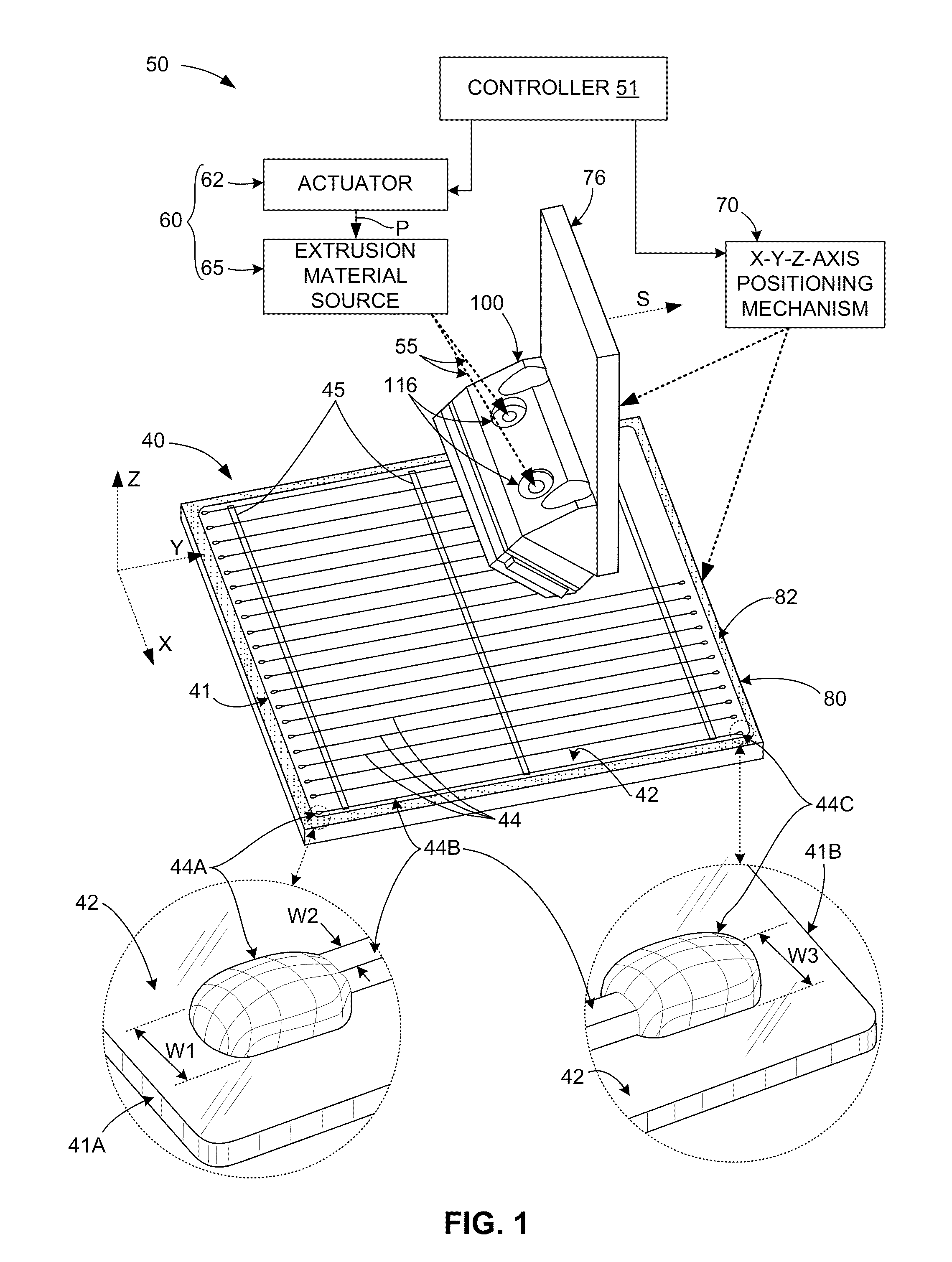
[0039]FIG. 1 is a simplified diagram illustrat...


PUM


Abstract

An H-pattern solar cell structure includes at least one busbar disposed in a first direction on an upper surface of a semiconductor substrate, and parallel gridlines formed on the semiconductor substrate such that each gridline extends over and contacts each busbar, wherein each gridline includes a central gridline portion and at least one endpoint structure disposed on at least one end thereof, the endpoint structure having a nominal width that is at least 1.5 times the width of the central gridline portion. The gridlines are co-extruded with a sacrificial material such that a base portion of each gridline forms a flattened structure with sacrificial material formed thereon. The endpoint structures are formed such that Each central gridline portion forms a raised vertex portion extending upward from the upper surface of each busbar.

Description

RELATED APPLICATIONS[0001]This application is a continuation-in-part of U.S. Patent application for “MICRO-EXTRUSION SYSTEM WITH AIRJET ASSISTED BEAD DEFLECTION”, U.S. application Ser. No. 12 / 267,223, filed Nov. 7, 2008.FIELD OF THE INVENTION[0002]This invention relates to systems and methods for producing solar cells, and more particularly to micro-extrusion systems and methods for producing H-pattern solar cells.BACKGROUND OF THE INVENTION[0003]Co-extrusion is useful for many applications, including inter-digitated pn junction lines, conductive gridlines for solar cells, electrodes for electrochemical devices, etc.[0004]In order to meet the demand for low cost large-area semiconductors, micro-extrusion methods have been developed that include extruding a dopant bearing material (dopant ink) along with a sacrificial material (non-doping ink) onto the surface of a semiconductor substrate, and then heating the semiconductor substrate such that the dopant disposed in the dopant ink di...

Claims


Application Information

Patent Timeline
IPC IPC(8): H01L31/04
CPCH01L21/6715Y02E10/50H01L31/022425
Inventor FORK, DAVID K.SOLBERG, SCOTT E.
Owner SOLARWORLD IND GMBH
Why Eureka
Try Eureka