Fuel Injector

a technology for injectors and internal combustion engines, which is applied in the direction of fuel injection apparatus, machine/engines, feed systems, etc., can solve the problems of reducing the accuracy of nozzle hole machining and increasing the manufacturing cost of fuel injectors, so as to reduce the length of the gap flow formed by the valve element and the seat section, reduce the resistance of flow path, and reduce the effect of pressure loss

Inactive Publication Date: 2010-12-23
HITACHI ASTEMO LTD
View PDF7 Cites 34 Cited by
  • Summary
  • Abstract
  • Description
  • Claims
  • Application Information

AI Technical Summary

Benefits of technology

[0018]Firstly, when the distance between the seat section and the opening start point decreases, the length of a gap flow formed by the valve element and the seat section decreases; flow path resistance decreases; pressure loss is reduced. As a result, the flow velocity increases. Therefore, when the distance between the seat section and the opening start point decreases, the flow rate into the nozzle hole opening increases.
[0019]Secondly, when the opening amplitude is great (that is, the opening change rate is high) while the distance between the seat section and the opening start point remains unchanged, the area of a flow path to the opening enlarges to increase the flow rate into the opening.
[0020]As described above, it is possible to individually

Problems solved by technology

Consequently, the time required for machining setup and post-machining inspection gets longer than when the diameters of all the nozzle holes are same, causing an increa

Method used


Image

  • Fuel Injector
  • Fuel Injector
  • Fuel Injector

Examples


Embodiment Construction

[0036]Embodiments of the present invention will now be described with reference to the drawings.

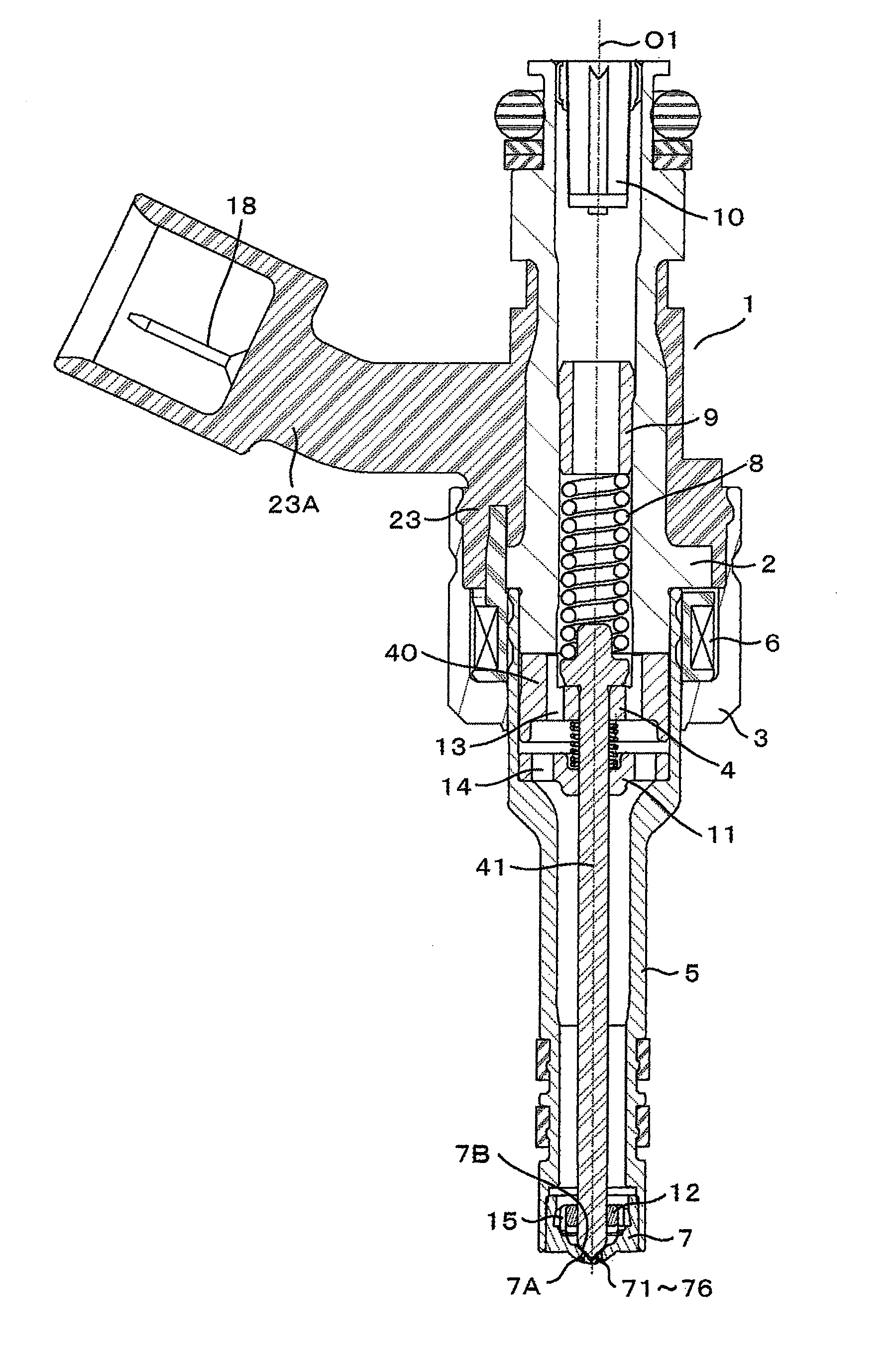
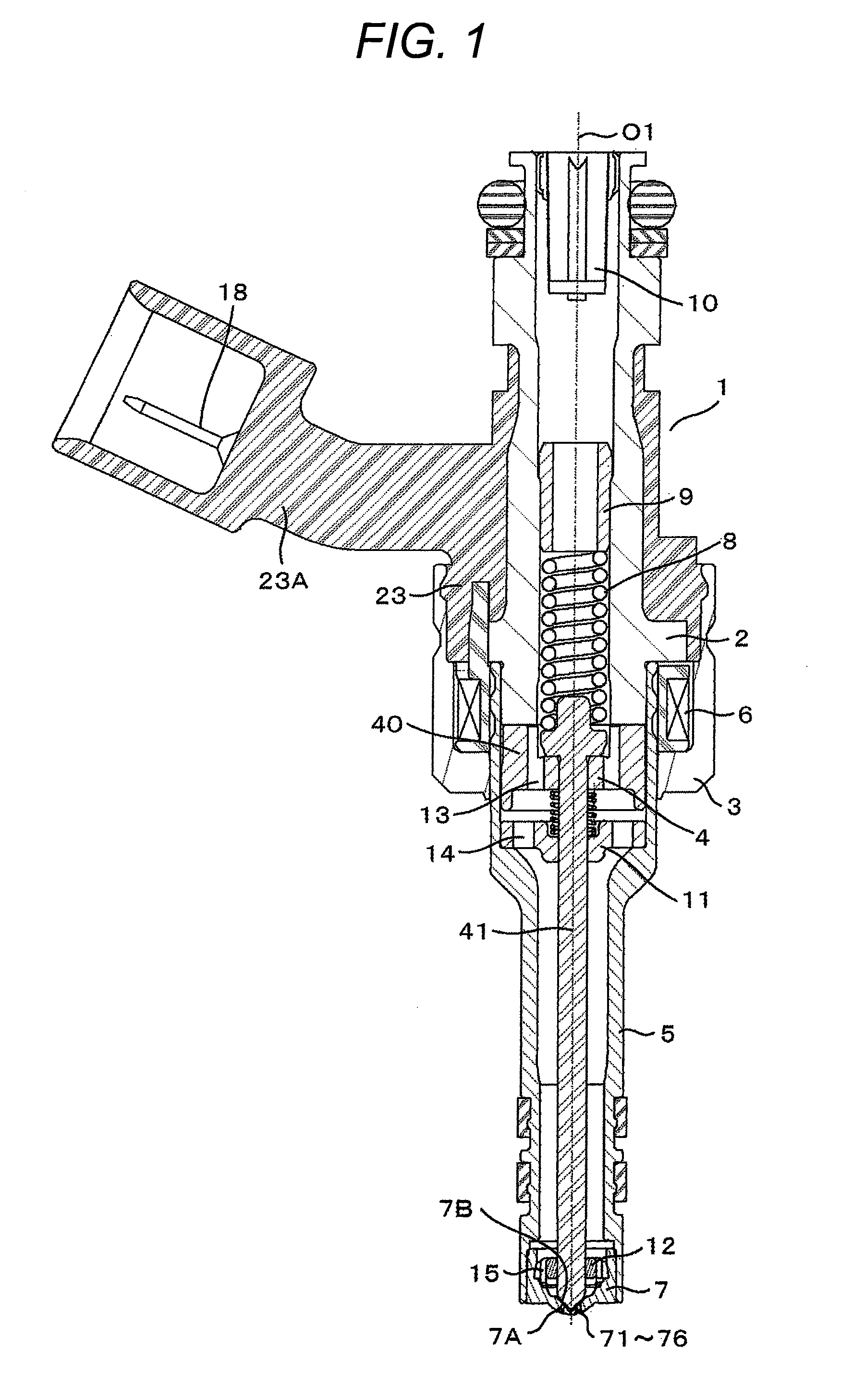
[0037]FIG. 1 is a longitudinal cross-sectional view illustrating the overall configuration of a fuel injector according to an embodiment of the present invention. The fuel injector according to the present embodiment directly injects gasoline or other fuel into an engine cylinder (combustion chamber).

[0038]A fuel injector main body 1 includes a hollow stationary core 2, a yoke 3, a movable element 4, and a nozzle body 5. The yoke 3 doubles as a housing. The movable element 4 includes a movable core 40 and a movable valve element 41. The stationary core 2, the yoke 3, and the movable core 40 constitute a magnetic circuit.

[0039]The yoke 3, the nozzle body 5, and the stationary core 2 are welded together. The welding operation may be performed in various manners. In the present embodiment, the nozzle body 5 and the stationary core 2 are welded together with a part of the outer circumference ...


PUM


Abstract

A fuel injector is disclosed that has plural nozzle holes with the same cross-sectional shape and can individually set the flow rate of each nozzle hole. The fuel injector includes the plural nozzle holes, a seat section positioned upstream of the nozzle holes, a valve element that closes a valve when brought into contact with the seat section and opens the valve when separated from the seat section, and a circular cone tapered from an upstream end to a downstream end and provided with the seat section and an inlet opening of the nozzle holes. The plural nozzle holes have an identical shape and a shape of a cross-section of each of the nozzle holes is substantially out-of-round, the cross-section being perpendicular to a central axis of each of the nozzle holes. The cross-section of each of the nozzle holes is rotated around the central axis of each of the nozzle holes. A rotation angle of the cross-section is set in such a manner that a relationship between a conical surface of the circular cone and the rotation angle is different among at least two of the nozzle holes.

Description

CLAIM OF PRIORITY[0001]The present application claims priority from Japanese Patent Application JP 2009-144871 filed on Jun. 18, 2009, the content of which is hereby incorporated by reference into this application.FIELD OF THE INVENTION[0002]The present invention relates to a fuel injector for an automotive internal combustion engine.BACKGROUND OF THE INVENTION[0003]An electromagnetic fuel injector driven by an electrical signal from an engine control unit is widely used in automotive internal combustion engines.[0004]This type of fuel injector is classified as either a port-injection type or a direct-injection type. A fuel injector of the port-injection type is mounted on an intake piping and injects fuel indirectly into a combustion chamber, whereas that of the direct-injection type injects fuel directly into the combustion chamber.[0005]In the fuel injector of the direct-injection type, the spray shape formed by the injected fuel determines the combustion performance. To obtain d...

Claims


Application Information

Patent Timeline
IPC IPC(8): F02M61/00
CPCF02M61/1846F02M51/0685
Inventor OGURA, KIYOTAKANAMAIZAWA, YASUO
Owner HITACHI ASTEMO LTD
Why Eureka
Try Eureka