Drive Mechanism for a Vehicle Propellable by Muscle Power and Vehicle

Inactive Publication Date: 2010-12-23
GRADITECH ENTWICKLUNGS
View PDF6 Cites 22 Cited by
  • Summary
  • Abstract
  • Description
  • Claims
  • Application Information

AI Technical Summary

Benefits of technology

[0008]There may be a need to create a drive mechanism for a driving shaft, in particular a cam disk of

Problems solved by technology

However, such a spiral spring is a further complex element and may be prone to failure and may brak

Method used


Image

  • Drive Mechanism for a Vehicle Propellable by Muscle Power and Vehicle
  • Drive Mechanism for a Vehicle Propellable by Muscle Power and Vehicle
  • Drive Mechanism for a Vehicle Propellable by Muscle Power and Vehicle

Examples


Embodiment Construction

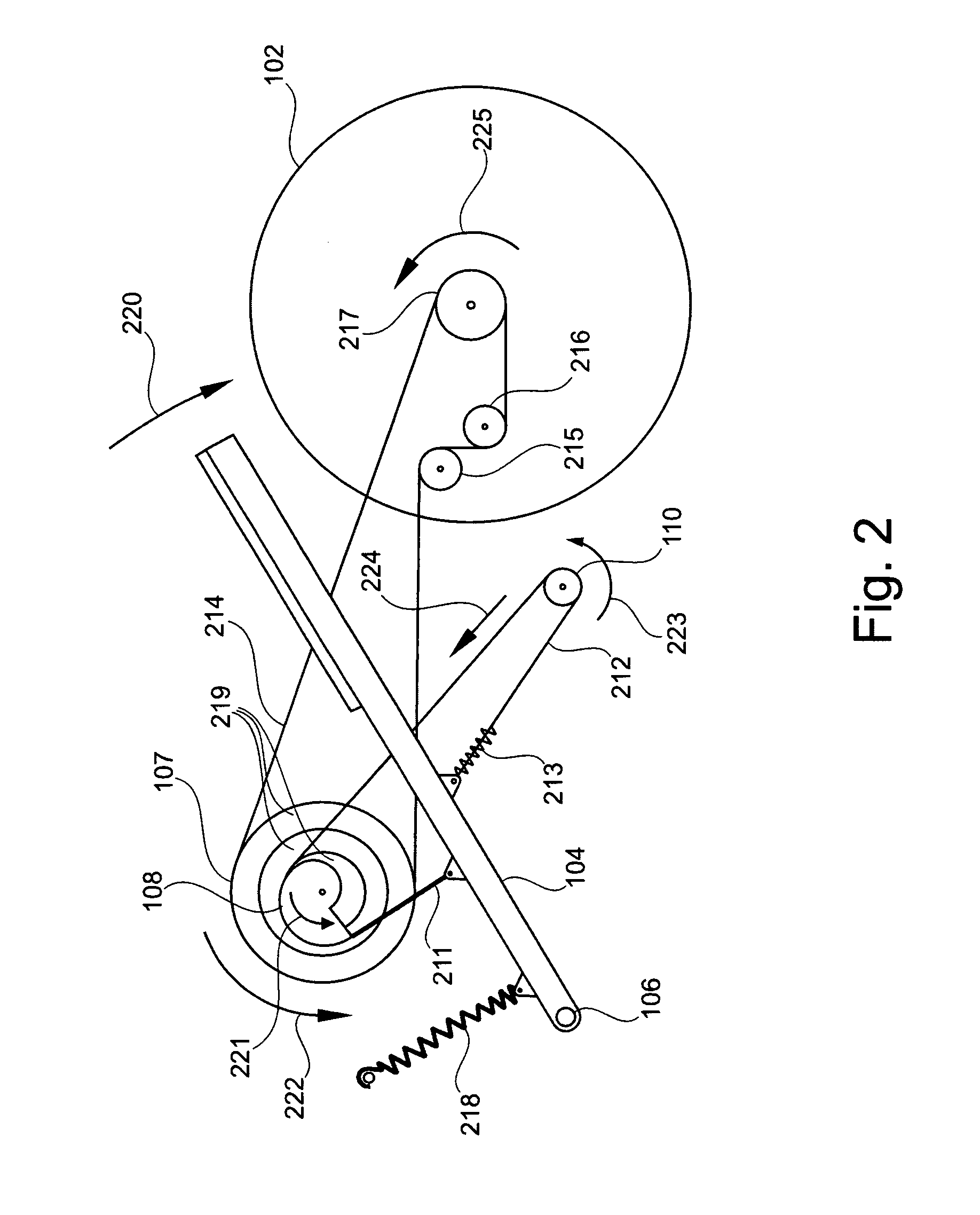
[0040]The illustration in the drawing is schematically. In different drawings, similar or identical elements are provided with the same reference signs.

[0041]In the following, referring to FIGS. 1 to 5 some basic principles of a drive mechanism and a vehicle according to exemplary embodiments will be explained.

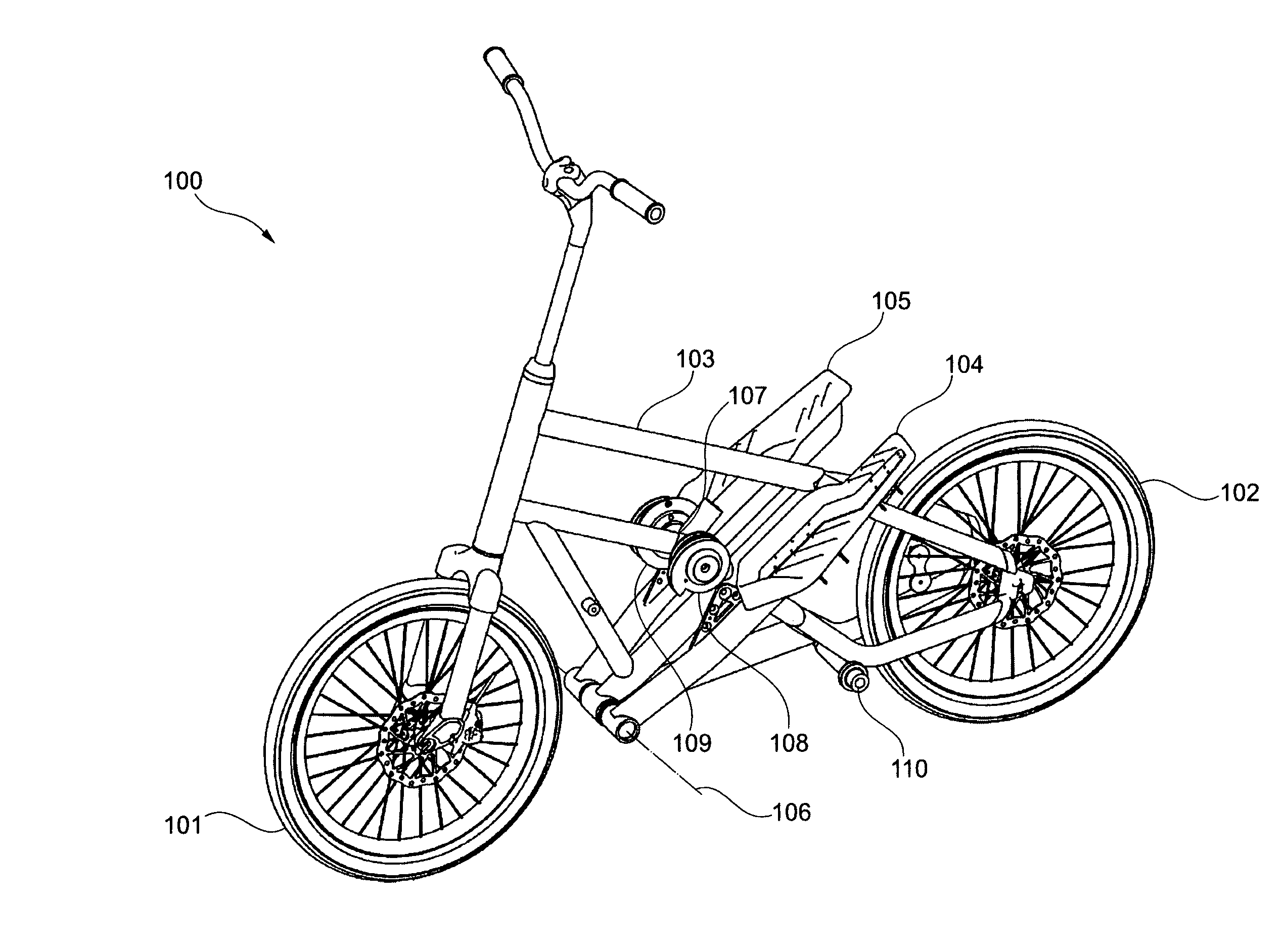
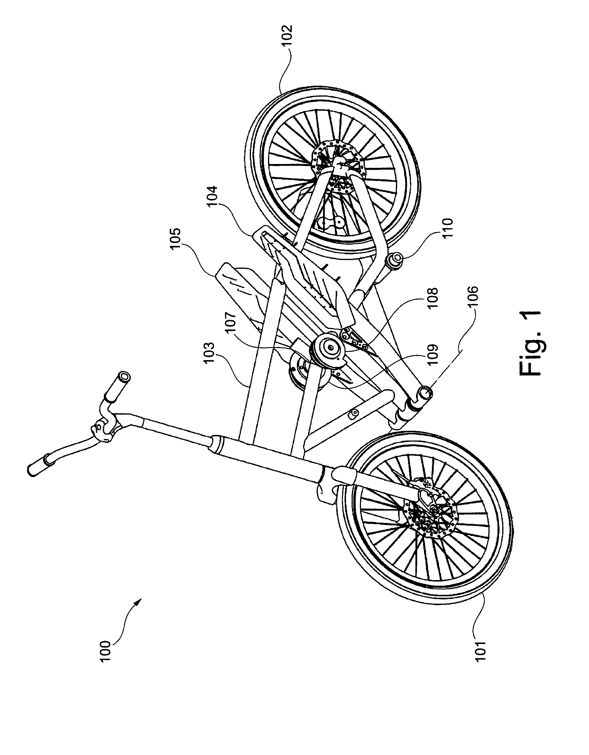
[0042]FIG. 1 schematically illustrates an overall view of a vehicle 100 according to an exemplary embodiment of the invention. In particular, the vehicle 100 is a step scooter which comprises, beside two wheels 101 and 102, a frame 103, and a drive mechanism according to an exemplary aspect of the invention. For the sake of clarity further known elements, e.g. brakes, lights, are not depicted in FIG. 1. The drive mechanism comprises two actuating elements 104 and 105 which can be moved independently from each other around an axle schematically indicated by the dotted line 106. The actuating elements form treads or levers which can be actuated by a driver along a stroke path. F...


PUM


Abstract

A drive mechanism for a vehicle propellable by muscle power is provided, wherein the drive mechanism comprises a first actuating element (104) which is moveable by a stroke along a movement path, a first driving element (211), a first gearing comprising a driving shaft (107), and first returning element (212), wherein the first driving element (211) is coupled between the first actuating element (104) and the driving shaft (107) in such a way that actuating element stroke induces a movement of the driving shaft in a first direction, and wherein the returning element (212) is coupled between the first actuating element (104) and the driving shaft (107) in such a way that it induces a movement of the driving shaft in a second direction opposite to the first direction.

Description

FIELD OF THE INVENTION[0001]The invention relates to a drive mechanism for a vehicle propellable by muscle power, in particular a step scooter and to a step scoter.BACKGROUND OF THE INVENTION[0002]Exemplary embodiments of vehicles propelled by muscle power, which are driven by the driver by a first tread surface, which is movable via a tread surface stroke and which also comprise a steering device, are identified as pedal mobile, scooter, see-saw scooter or lever-propelled bicycle, for example. As a rule, such vehicles are equipped with one, but in particular with two such tread surfaces, for example in the form of levers, which are preferably alternately moved by the driver, in particular by using a treading motion. Oftentimes, the tread surface is supported so as to be pivotable about an axis in a certain angle. However, exemplary embodiments are also known in which the tread surface is not supported so as to be pivotable in a certain angle, but where the angle between tread surfa...

Claims


Application Information

Patent Timeline
IPC IPC(8): B62M1/04F16H21/52B62M1/24
CPCB62M1/28F16H19/0659Y10T74/18152Y10T74/18056F16H31/001
Inventor BUCHBERGER, MARTIN
Owner GRADITECH ENTWICKLUNGS
Why Eureka
Try Eureka