Microwave Ablation Antenna Radiation Detector

a radiation detector and microwave ablation technology, applied in the field of microwave antennas, can solve problems such as inadvertent radiation outside the tissu

Active Publication Date: 2010-12-23
TYCO HEALTHCARE GRP LP
View PDF16 Cites 49 Cited by
  • Summary
  • Abstract
  • Description
  • Claims
  • Application Information

AI Technical Summary

Problems solved by technology

In some instances this may result in inadvertent radiation outside the tissue.

Method used


Image

  • Microwave Ablation Antenna Radiation Detector
  • Microwave Ablation Antenna Radiation Detector
  • Microwave Ablation Antenna Radiation Detector

Examples


Embodiment Construction

[0017]Particular embodiments of the present disclosure will be described herein below with reference to the accompanying drawings. In the following description, well-known functions or constructions are not described in detail to avoid obscuring the present disclosure in unnecessary detail.

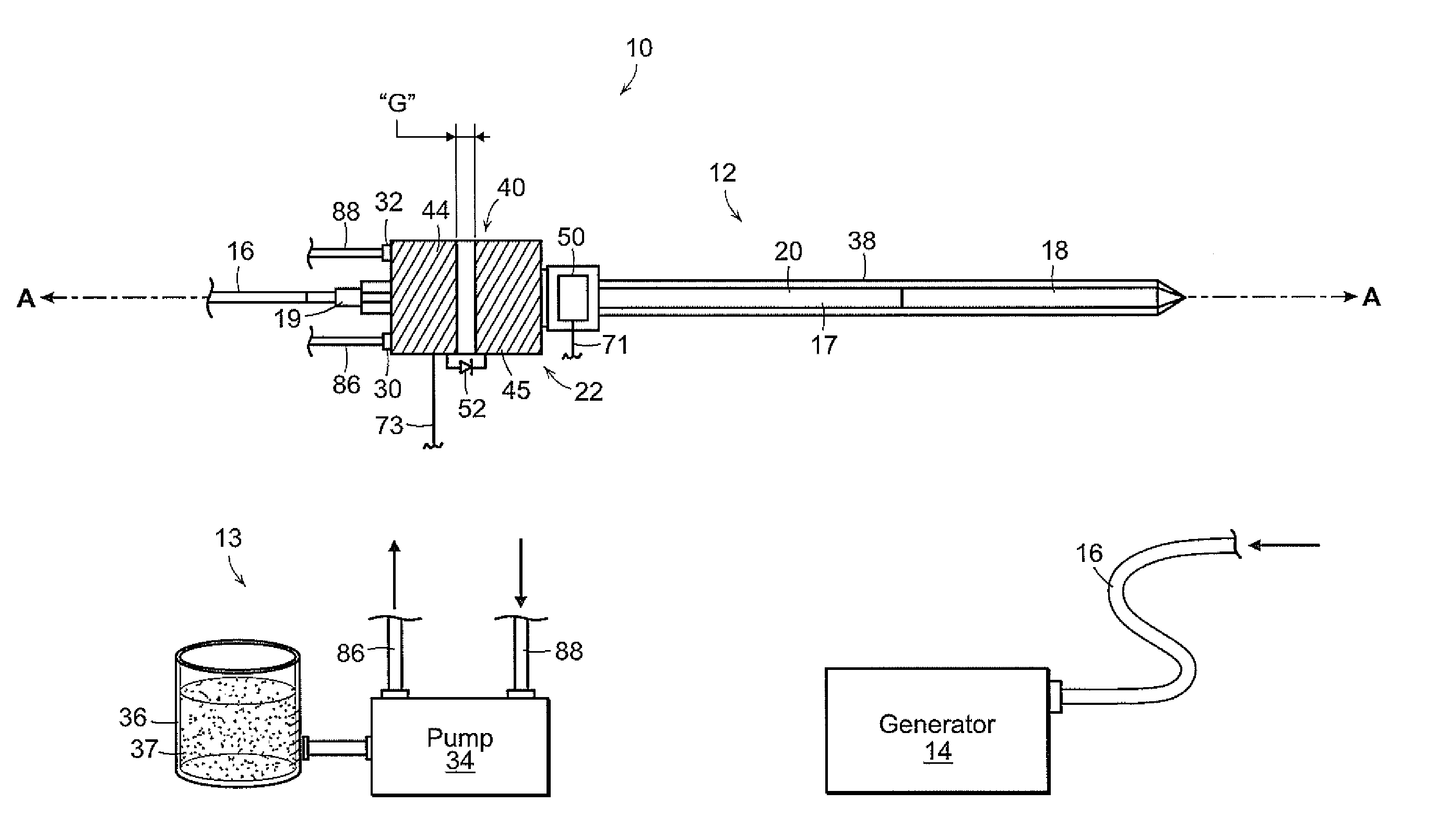
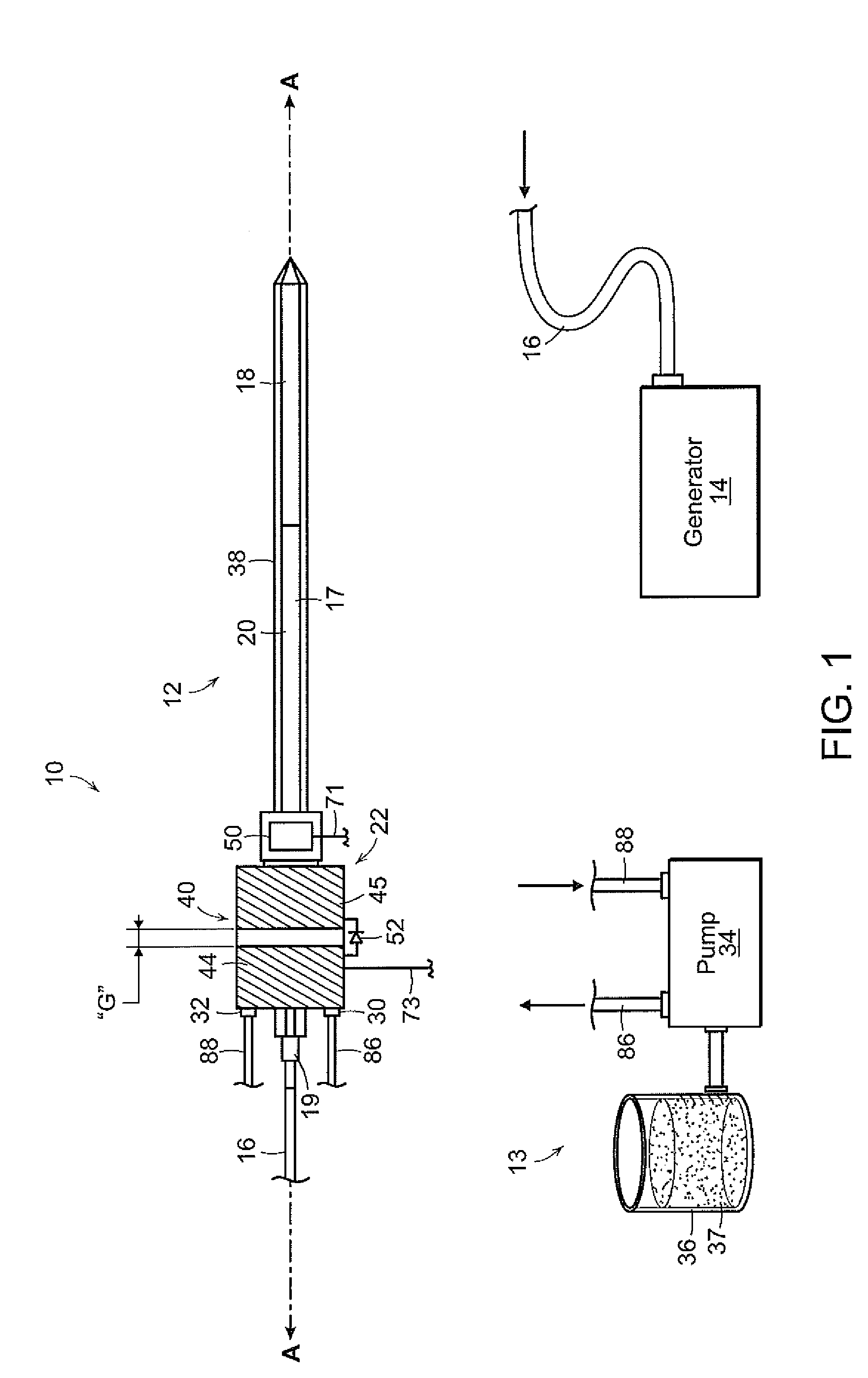
[0018]The present disclosure provides for a radiation detector disposed on a microwave antenna. Generally, the detector is disposed in a location such that any unintended and / or errant radiation of microwave energy along the antenna is detected. The radiation detector converts the detected radiation into a detection signal, which is then transmitted to a control system (e.g., microwave generator) to either shut off the power supply and / or alert the user.

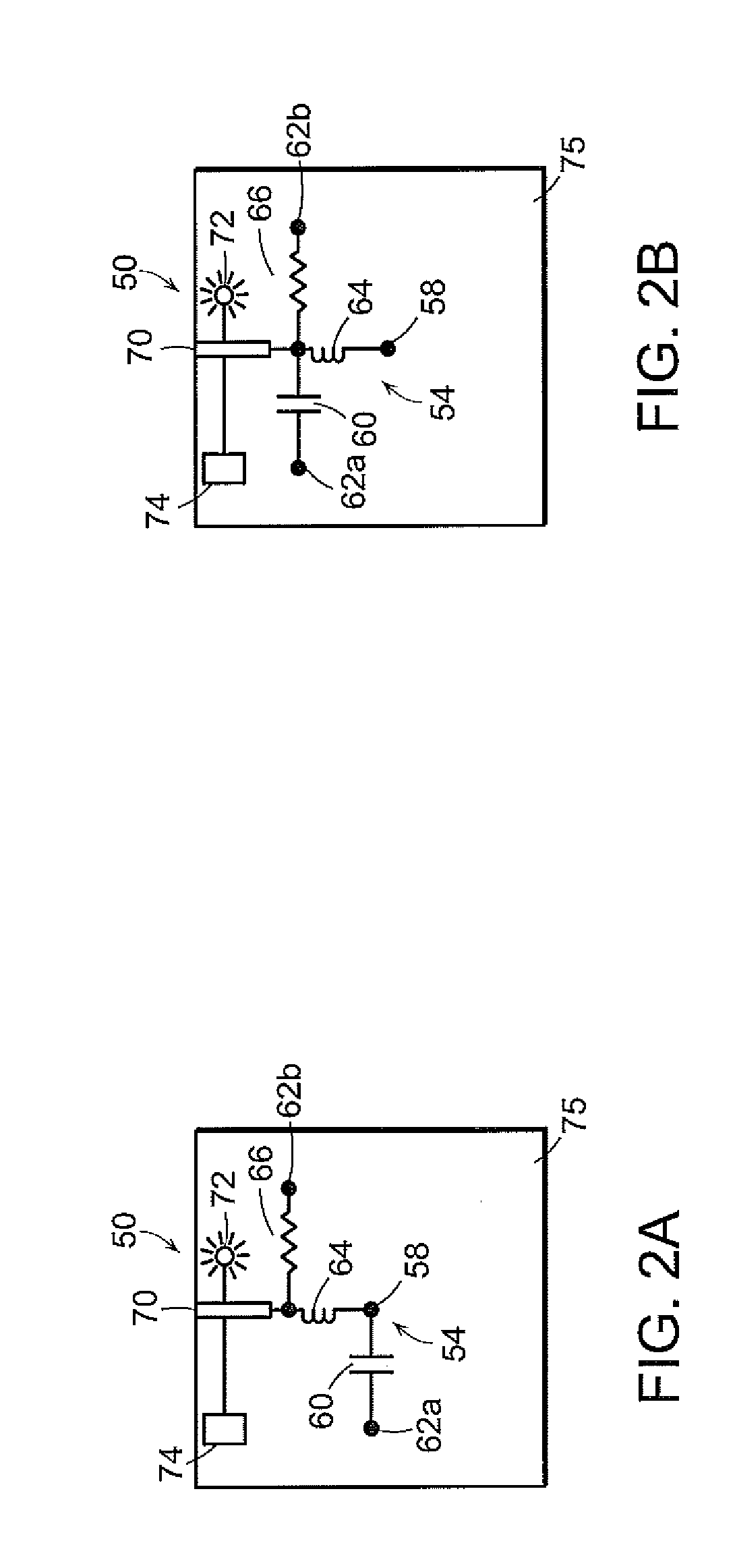
[0019]In one embodiment, the radiation detector includes a receiving antenna adapted to receive microwave energy radiating along the microwave antenna and a rectifying circuit including a rectifying device and a filter. The rectifying circuit recti...


PUM


Abstract

A radiation detector is disclosed. The radiation detector is disposed on a microwave antenna assembly. The radiation detector includes a receiving antenna adapted to receive microwave energy. The receiving antenna includes a first tubular antenna member and a second tubular antenna member disposed concentrically about a longitudinal axis defined by the microwave antenna assembly. The detector also includes at least one rectifier coupled to the receiving antenna adapted to rectify at least a portion of the microwave energy and a filter coupled to the at least one rectifier and adapted to convert the rectified microwave energy into a detection signal.

Description

CROSS-REFERENCE TO RELATED APPLICATION[0001]The present application is a continuation-in-part of a U.S. application Ser. No. 12 / 487,917 titled “Microwave Ablation Antenna Radiation Detector” by Joseph D. Brannan on Jun. 19, 2009, which is hereby incorporated by reference.BACKGROUND[0002]1. Technical Field[0003]The present disclosure relates generally to microwave antennas. More particularly, the present disclosure is directed to radiation detectors for microwave ablation antennas.[0004]2. Background of Related Art[0005]Treatment of certain diseases requires destruction of malignant tissue growths (e.g., tumors). It is known that tumor cells denature at elevated temperatures that are slightly lower than temperatures injurious to surrounding healthy cells. Therefore, known treatment methods, such as hyperthermia therapy, heat tumor cells to temperatures above 41° C., while maintaining adjacent healthy cells at lower temperatures to avoid irreversible cell damage. Such methods involve ...

Claims


Application Information

Patent Timeline
Patent Type & Authority Applications(United States)
IPC IPC(8): G01R29/08
CPCA61B18/1492A61B18/1815A61B2017/00039H01Q1/273H01Q1/247H01Q1/248G01R29/0878
Inventor BRANNAN, JOSEPH D.
Owner TYCO HEALTHCARE GRP LP
Why Eureka
Try Eureka