Computer server chassis

a server chassis and server technology, applied in the direction of electrical apparatus casings/cabinets/drawers, process and machine control, instruments, etc., can solve the problems of likely failure of the fan and likely cooling inefficiency, and achieve steady state, increase the power or current of the fan, and increase the airflow

Inactive Publication Date: 2010-12-23
INTELICLOUD TECH
View PDF6 Cites 46 Cited by
  • Summary
  • Abstract
  • Description
  • Claims
  • Application Information

AI Technical Summary

Benefits of technology

[0008]In particular, a scalable rack mounted computer equipment is provided. The equipment may have a rack, a plurality of computer components, an air exhaust plenum and an air intake plenum. The computer components may be stacked upon each other and attached to vertical attachment points of the rack. Each of the computer components may have an airflow path between a top and bottom of the computer component. The air may flow between vertically adjacent computer components. By way of example and not limitation, air may flow from a lower computer component through a middle computer component and out of an upper computer component. Alternatively, air may flow through the air intake plenum, through an adjacent upper computer component and out of the upper computer component. Additionally, air may flow through a lower computer component through the upper computer component and out of the air exhaust plenum. Since the air exhaust plenum and air intake plenum are separate from the computer component, one or more computer components may be disposed between the air intake plenum and the air exhaust plenum for scaling the amount of computer components necessary for the computing task at hand. The air intake plenum may be disposed below the stacked computer components and the air exhaust plenum may be disposed above the stacked computer components. Alternatively, the reverse configuration is also contemplated.
[0009]An energy efficient cooling computer component is disclosed herein. The energy efficient computer component has a plurality of fans which control airflow through a plurality of zones. Based on the cooling requirement for each of the zones, each of the fans spin at a different speed thereby flowing a different amount of air through their respective zone. Accordingly, when a local area within the server chassis requires additional cooling, the zone of that increased heat area receives increased airflow. The other zones to the extent possible are left unaffected. As such, only the fan with the effected heat area requires additional energy.
[0010]A method for determining fan failure despite the existence of air flow clogging as disclosed. A calibration line curve is a data set or function which plots airflow blockage percentage on the x axis and current on the y axis. The calibration curve line is determined (1) for each chassis since each chassis will or may have different airflow characteristics and (2) for a range of fan speeds (e.g., fan blade rotations per minute, etc.). During operation, after airflow blockage occurs, the airflow blockage percentage due to the occurrence of the airflow blockage is determined. Steady state cooling is achieved by increasing power or current to the fan. The current applied to the fan is determined. If the current is above the calibration curve line for the determined airflow blockage percentage, then fan failure is likely. If the current is below the calibration curve line for the determined airflow blockage percentage, then cooling inefficiency is probably due to airflow blockage and not fan failure.

Problems solved by technology

If the current is above the calibration curve line for the determined airflow blockage percentage, then fan failure is likely.
If the current is below the calibration curve line for the determined airflow blockage percentage, then cooling inefficiency is probably due to airflow blockage and not fan failure.

Method used


Image

  • Computer server chassis
  • Computer server chassis
  • Computer server chassis

Examples


Embodiment Construction

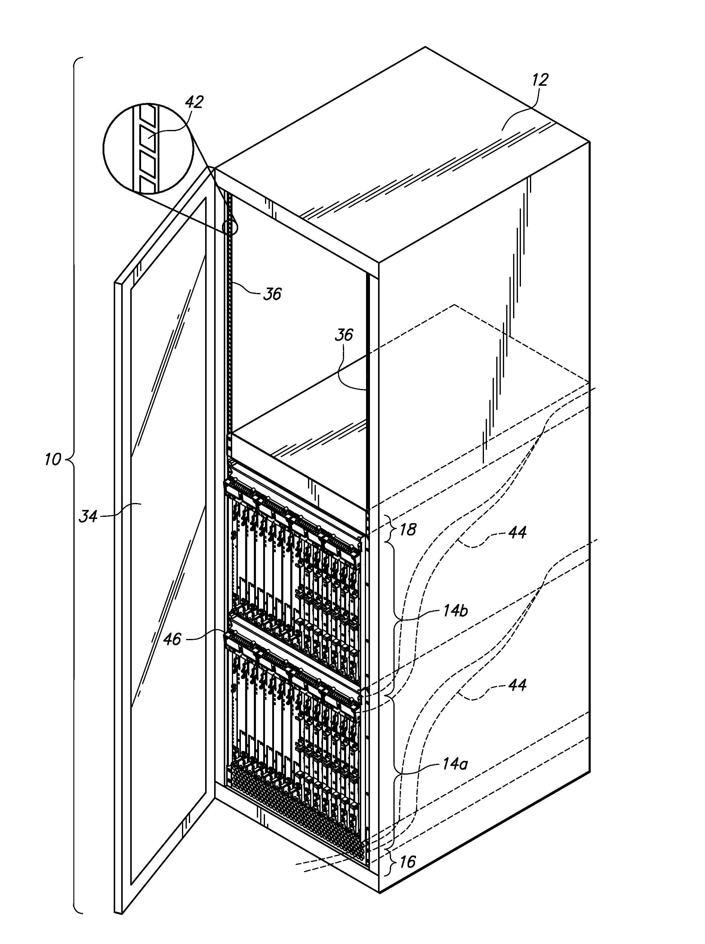
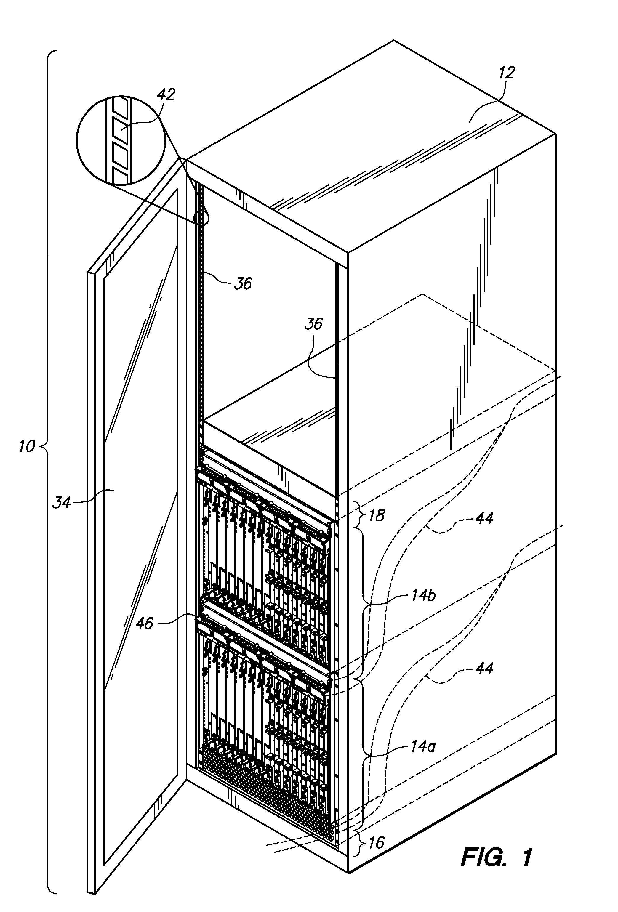
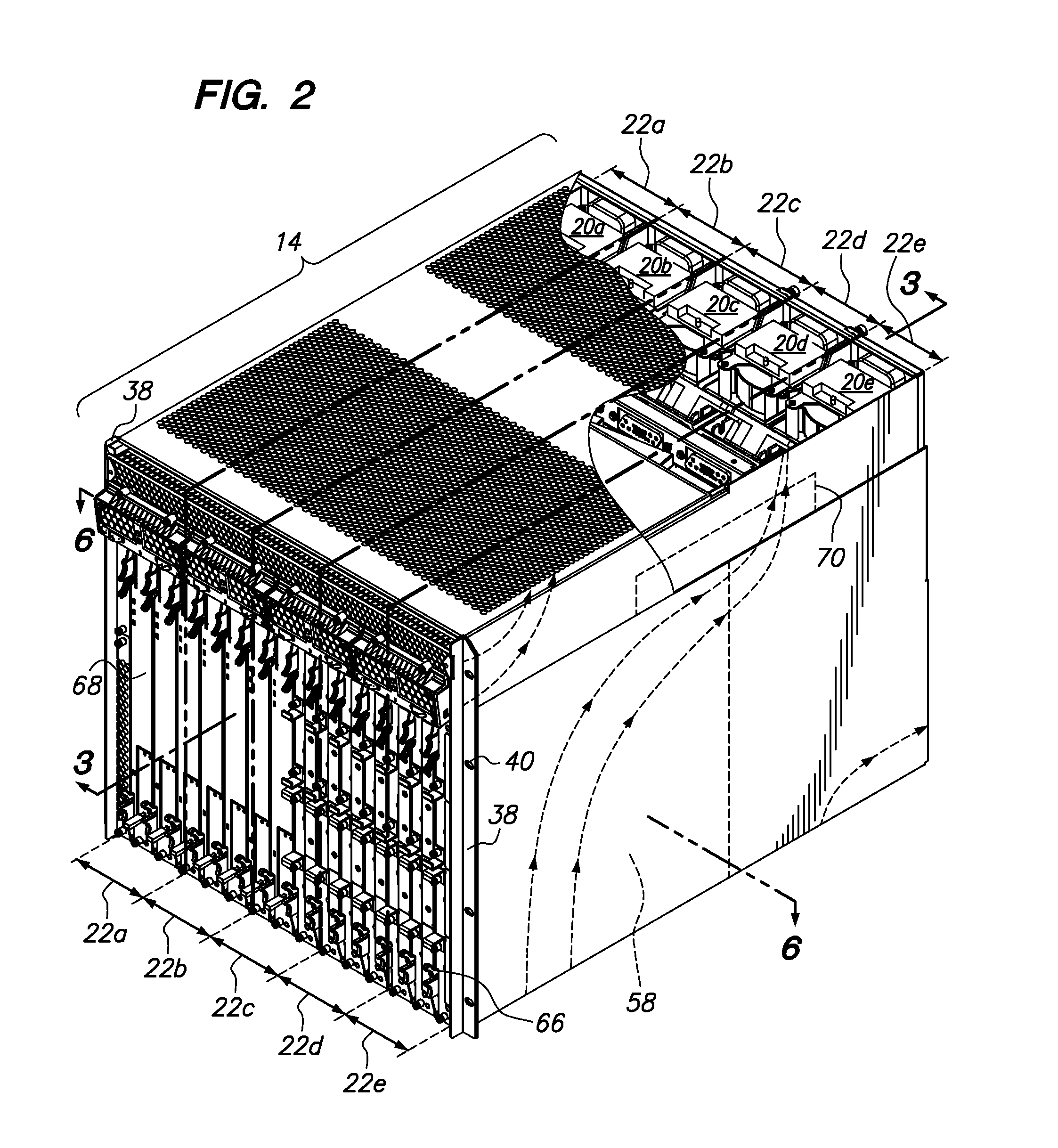
[0020]Referring now to FIG. 1, a server housing 10 is shown. The server housing 10 comprises an enclosure 12. One or more server chassis 14 is mountable to the enclosure 12 with an intake plenum 16 and exhaust plenum 18 disposed on opposed upper and lower sides of the one or more stacked server chassis mounted to the enclosure 12. The server capabilities are expandable or reconfigurable after setup by inserting additional or removing server chassis 14 between the intake plenum 16 and the exhaust plenum 18. Additionally, each server chassis 14 may have a plurality of fans 20a-e, as shown in FIG. 2. Each of the fans 20a-e may independently increase or decrease an amount of air flowing through a particular zone within the server chassis 14 to efficiently increase airflow through a particular zone when needed and decrease airflow through a particular zone 22a-e when not needed. Moreover, each of the fans 20a-e is set to a particular fan speed based on a temperature differential at an ai...


PUM


Abstract

An expandable server housing having one or more server chassis stacked upon each other and one intake plenum and one exhaust plenum disposed on opposite sides of the stacked server chassis is disclosed. Each server chassis may have two or more fans predominately controlling airflow rate through a zone of the server chassis. Also, a method and system determining fan failure regardless of blockage of air path.

Description

CROSS-REFERENCE TO RELATED APPLICATIONS[0001]This application relates to and claims the benefit of U.S. Provisional Application No. 61 / 218,357 filed Jun. 18, 2009 and entitled Improved Computer Server Chassis, the entire content of which is wholly incorporated by reference herein.STATEMENT RE: FEDERALLY SPONSORED RESEARCH / DEVELOPMENT[0002]Not ApplicableBACKGROUND[0003]The present invention relates to a scalable server housing, an energy efficient cooling system and a method for distinguishing fan failure versus air blockage.[0004]In prior art server housings, a plurality of server chassis may be mounted to the server enclosure. Each of the server chassis has its own intake plenum and exhaust plenum for cooling which does not interact with the cooling system of other server chassis in an integratable way. As a result, prior art server chassis have limited scalability to either add additional server chassis to the enclosure or to remove server chassis from the enclosure.[0005]Addition...

Claims


Application Information

Patent Timeline
Patent Type & Authority Applications(United States)
IPC IPC(8): H05K7/20G06F19/00G01F1/56G05D23/19
CPCH05K7/20736
Inventor BHATTACHARYYA, NEELOYBYRD, TIM
Owner INTELICLOUD TECH
Why Eureka
Try Eureka