Scalpel handle

a technology of handle and blade, which is applied in the field of scalpel handle devices, can solve the problems of increasing the chance of minor hand tremor or misalignment of the blade relative to the surgical site, affecting so as to reduce the need to hold the handle in a different way, improve the accuracy of incisions, and facilitate the effect of holding

Active Publication Date: 2010-12-23
UNIV OF MASSACHUSETTS
View PDF34 Cites 10 Cited by
  • Summary
  • Abstract
  • Description
  • Claims
  • Application Information

AI Technical Summary

Benefits of technology

[0006]A preferred embodiment of the invention uses a contoured handle having a generally circular cross-section along its longitudinal length. This shape enables the surgeon to freely rotate the scalpel blade to different angles to reduce the need to hold the handle differently. The handle has a double trough shape where the central portion of the handle has a larger diameter and is positioned centrally relative to two narrower diameter regions or troughs that are contoured for manual grasping by the surgeon.
[0007]This present invention further relates to an adapter sleeve that can be attached to a scalpel blade. The adapter sleeve provides a handle that is easier to hold, thereby giving the surgeon greater control and ability to make more precise incisions. The adapter sleeve of the present invention includes a cavity extending through a portion of the sleeve that receives the proximal end or handle of the scalpel such that the blade extends from the distal end of the adapter. An outer surface region of the adapter sleeve includes a handle portion that is gripped manually by the hand of the user during a surgical procedure. The sleeve handle has a contoured surface to provide for proper orientation of the blade of the scalpel relative to the surgical site. The contoured surface of the handle can include a proximal section with a thicker diameter that tapers to a smaller diameter section at the distal end. The distal section can have a recess for the thumb of the user. The blade can be rigidly oriented relative to the surface features to improve manual manipulation. The sleeve handle can be left or right handed.

Problems solved by technology

Depending on the “handedness” of the surgeon one incision is more difficult to make than the other.
This is due to the traditional flat handle design used for most scalpels, which makes it much harder to hold the blade in the proper fashion.
The flat handle requires the surgeon's wrist to roll more for one incision versus the other, thus increasing the chance of a minor hand tremor or misalignment of the blade relative to the surgical site while cutting.
This in turn, reduces the precision with which minor image symmetry can be created.

Method used


Image

  • Scalpel handle
  • Scalpel handle
  • Scalpel handle

Examples


Embodiment Construction

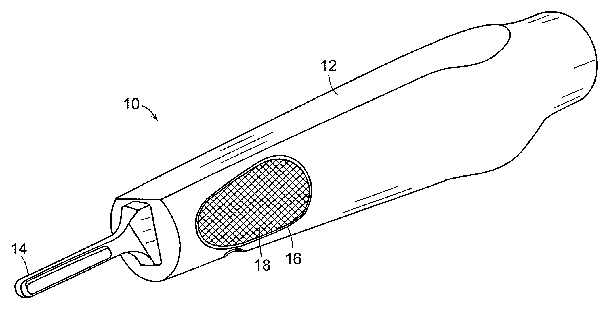
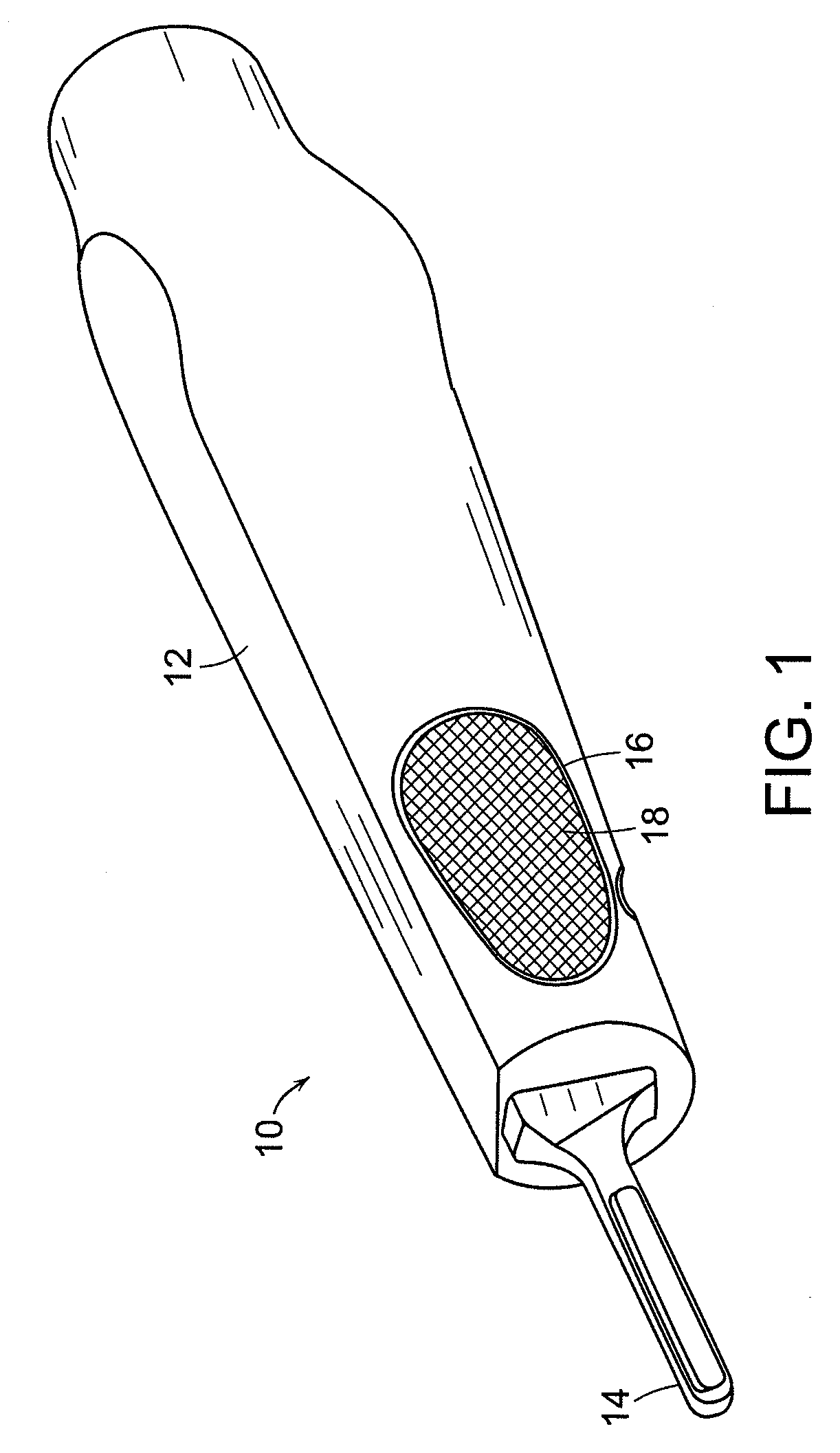
[0028]This invention describes an adapter sleeve that can be attached to existing flat handled scalpels. The adapter sleeve can be elliptical in shape at least along a portion thereof and crosshatched or beveled to make the handle a more natural feel thereby making it easier to hold to provide superior scalpel manipulations. In addition, the design can also be manufactured as a knife handle unit.

[0029]The adapter sleeve can be a sterilizable or disposable, elliptical-shaped, beveled plastic handle that can be used on existing scalpel handles. In addition to making the handle of the scalpel easier to hold, the design of the adapter also has the advantage of making the handle less slippery than the traditional steel handle. Through use of the adapter sleeve the scalpel will be easier to manipulate thereby allowing the precision of the incision to be increased.

[0030]A preferred embodiment of the invention is illustrated in connection with FIG. 1. The adapter sleeve scalpel device 10 of...


PUM


Abstract

The present invention relates to a contoured scalpel handle. The contoured shape of the handle provides for increased contact area with the user's hand using a larger diameter central portion and a smaller diameter trough. The generally circular cross-section allows rotation of the angle of the blade relative to the tissue without the need to change the grip on the handle. The contoured handle can be used as an adapter sleeve in which a scalpel handle can be inserted or can include a blade mounting element on which a blade is directly mounted.

Description

CROSS REFERENCE TO RELATED APPLICATIONS[0001]This is a continuation-in-part application of U.S. application Ser. No. 11 / 662,716 filed on Mar. 13, 2007, which is a U.S. National Phase Application of International Application No. PCT / US05 / 032416 filed on Sep. 13, 2005, which claims the benefit under 35 U.S.C. 119(e) of U.S. Provisional Application No. 60 / 609,430, filed Sep. 13, 2004, the disclosure of the above referenced application being incorporated herein by reference.BACKGROUND OF THE INVENTION[0002]Surgeons have traditionally used scalpels for a variety of surgical procedures to cut or excise tissue. Surgical precision requires, in certain types of procedures, the angle of orientation of the scalpel blade to be of particular importance.[0003]For example, each year many people have skin growths, such as moles, removed. In order to excise the mole the surgeon must use a scalpel to make two mirror image incisions in the skin around the mole. Depending on the “handedness” of the sur...

Claims


Application Information

Patent Timeline
Patent Type & Authority Applications(United States)
IPC IPC(8): A61B17/3213
CPCA61B17/3213A61B2017/0046A61B2017/00424
Inventor DUNN, RAYMOND
Owner UNIV OF MASSACHUSETTS
Why Eureka
Try Eureka