Method for establishing a desired area of confinement for an autonomous robot and autonomous robot implementing a control system for executing the same

a technology of autonomous robots and control systems, applied in the field of autonomous robots, can solve the problems of unnecessarily complex commercially successful robots, damaged robots, and injury to unsuspecting peopl

Active Publication Date: 2010-12-23
ROBOLABS +1
View PDF18 Cites 94 Cited by
  • Summary
  • Abstract
  • Description
  • Claims
  • Application Information

AI Technical Summary

Problems solved by technology

Each of these robots has faced a similar challenge: how to define the bounding area with minimal effort and efficiently cover the designated area given limited energy reserves.
Commercially successful robots tend to be unnecessarily complex and generally operate randomly within a confined area.
In existing technologies, problems may arise with the physically defined perimeter, thereby enabling the autonomous robot to leave the desired area of confinement.
Among other things, these failures can lead to a damaged robot, injury to an unsuspecting person, or failed coverage.
As described above, if an autonomous robot is able to leave the desired area of confinement, the coverage will obviously not be optimal.
Furthermore, existing technologies require the installation of a physical barrier, possibly including burying a perimeter wire around the desired area.
This is not the easiest possible use of an autonomous robot designed to be contained in a bounded area for lawn mowing.

Method used


Image

  • Method for establishing a desired area of confinement for an autonomous robot and autonomous robot implementing a control system for executing the same
  • Method for establishing a desired area of confinement for an autonomous robot and autonomous robot implementing a control system for executing the same
  • Method for establishing a desired area of confinement for an autonomous robot and autonomous robot implementing a control system for executing the same

Examples


Embodiment Construction

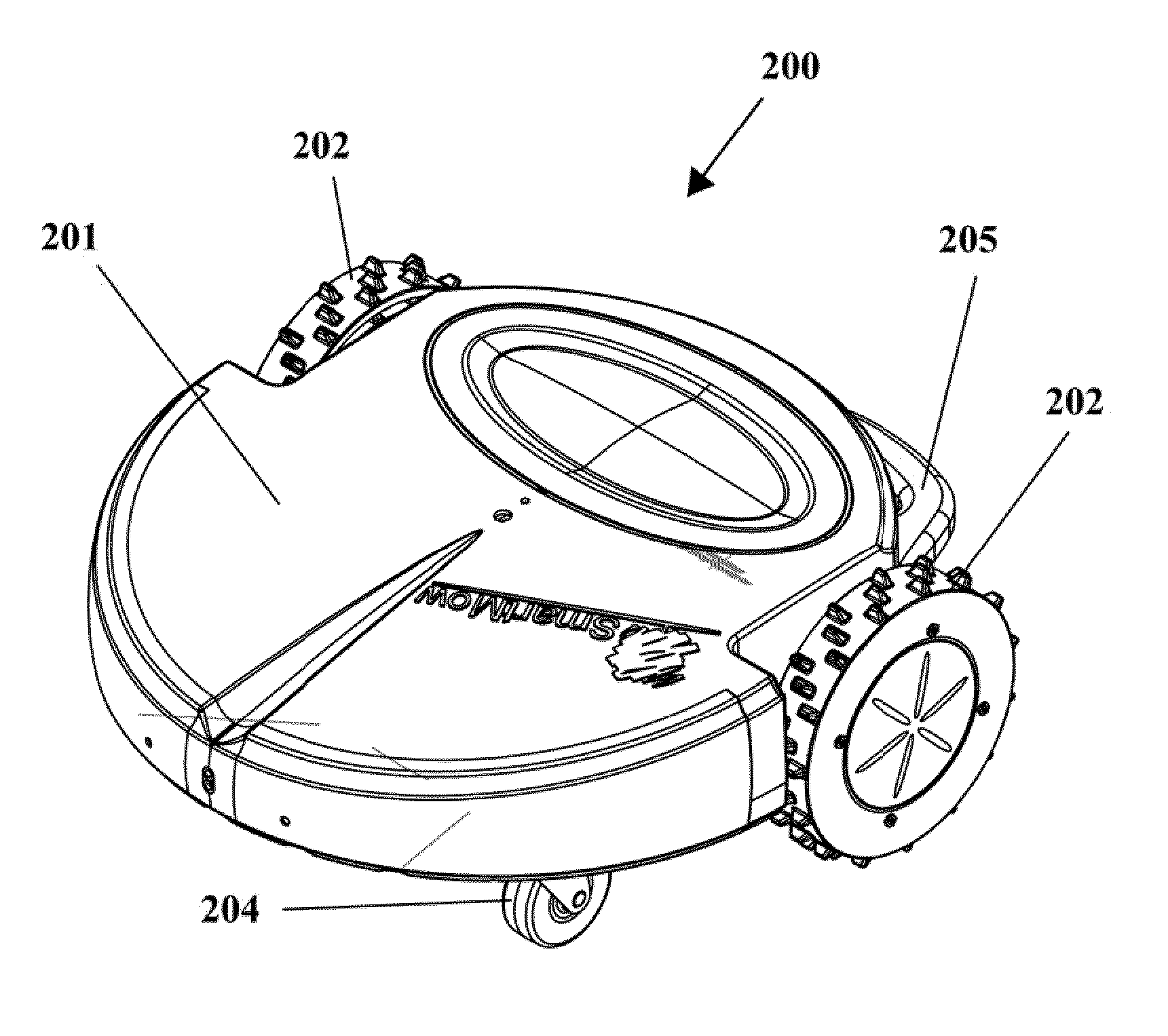
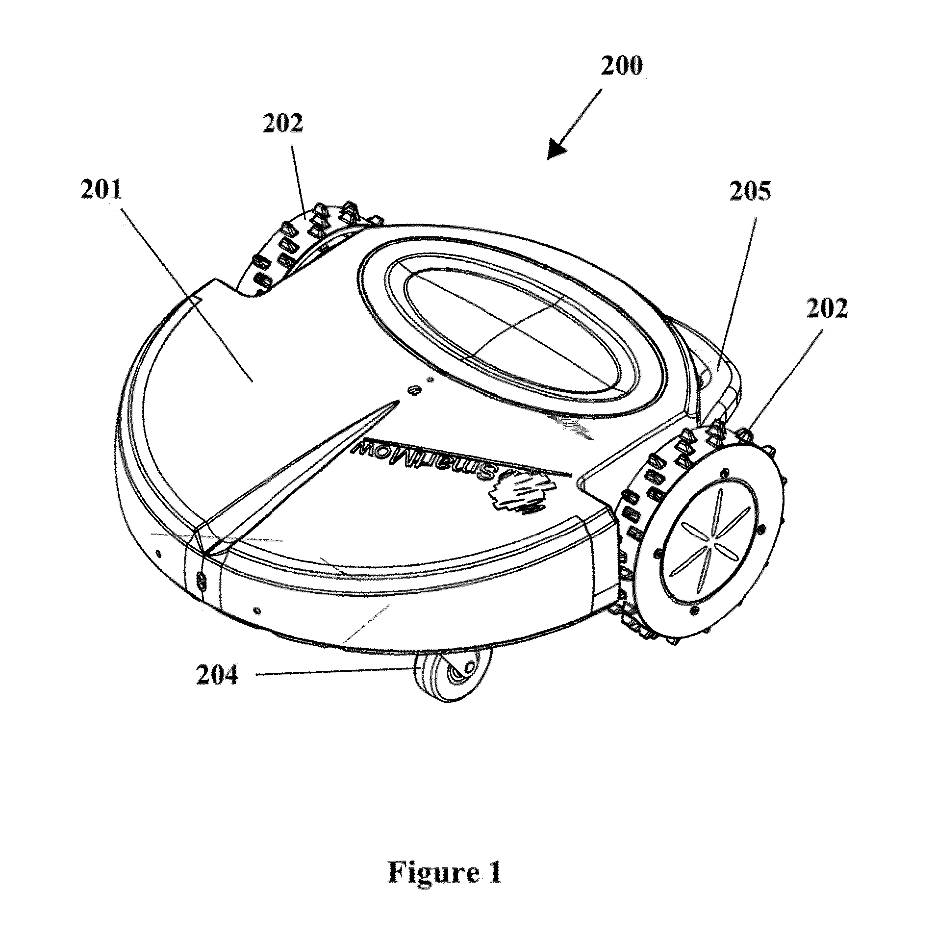
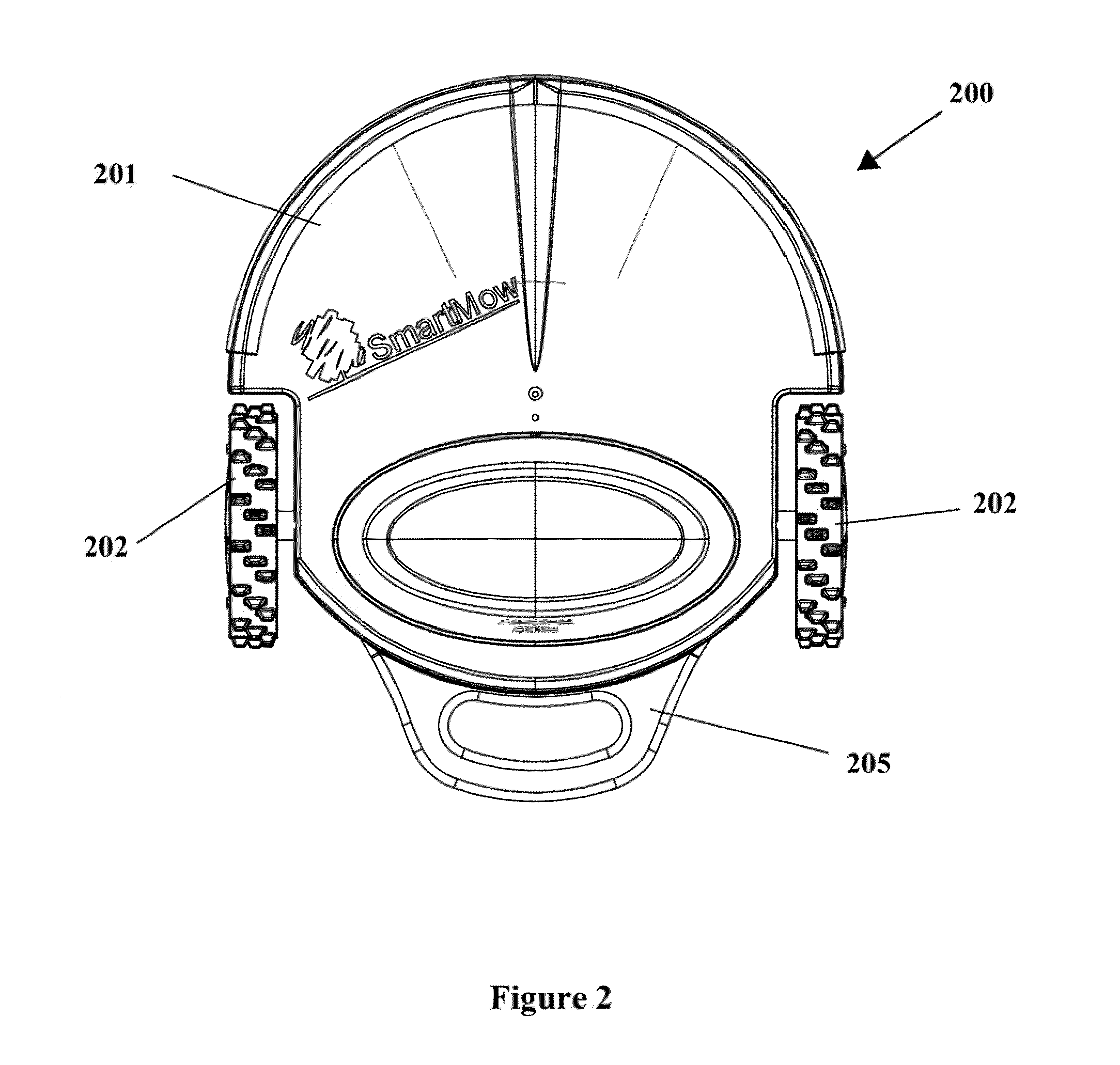
[0027]Referring first to FIGS. 1-7 concurrently, an autonomous robot 200 designed for mowing a lawn is illustrated according to one embodiment of the present invention. While the invention will be described in terms of an autonomous robot designed for mowing a lawn, it is to be understood that the control system and methods described herein can be implemented into any type of autonomous machine that must perform a desired activity within a desired area of confinement, including without limitation cleaning machines, polishing machines, repair machines, and / or demolition machines.

[0028]The autonomous robot 200 generally comprises a main housing 201, a pair of drive wheels 202, grass cutting blades 203 and steering wheels 204. A handle 205 is provided on the rear end of the housing 201 for convenience of handling and / or user-initiated movement. Three cutting blades 203 are provided. However, more or less blades 203 can be implemented.

[0029]Referring briefly to FIG. 13, the housing 201 ...


PUM


Abstract

A method of establishing an area of confinement and an autonomous robot for performing a task within the area of confinement. In one aspect, the invention can be a method of defining an area of confinement comprising: positioning the autonomous robot at a starting point P0 and recording the starting point P0 as a reference point within a memory device; moving the autonomous robot from the starting point P0 about a perimeter of the area of confinement, wherein said movement of the autonomous robot is controlled by a user; continuously tracking location of the autonomous robot relative to the reference point P0 during said movement using a distance-traveled measuring mechanism and a directional indicating instrument; recording the tracked location as a map in the memory device; and upon detecting that the map includes a closed-geometry, defining the closed-geometry as the perimeter of the area of confinement within the memory device.

Description

CROSS-REFERENCE TO RELATED APPLICATION[0001]The present application claims the benefit of U.S. Provisional Patent Application Ser. No. 61 / 218,279, filed Jun. 18, 2009, the entirety of which is hereby incorporated by reference.FIELD OF THE INVENTION[0002]This invention relates to the field of autonomous robots and, specifically to mobile robots that are designed to perform tasks within a bounded area, such as for performing cleaning or lawn mowing tasks.BACKGROUND OF THE INVENTION[0003]Autonomous robots that perform household functions such as floor cleaning and lawn mowing are now readily available consumer products. As found in the industry and elsewhere, numerous attempts have been made to build lawn mowing robots. Each of these robots has faced a similar challenge: how to define the bounding area with minimal effort and efficiently cover the designated area given limited energy reserves.[0004]Commercially successful robots tend to be unnecessarily complex and generally operate ra...

Claims


Application Information

Patent Timeline
Patent Type & Authority Applications(United States)
IPC IPC(8): B25J9/00
CPCA01D34/008A47L2201/00G05D1/0225G05D1/027G05D1/0272A47L2201/04G05D1/0278G05D1/028G05D2201/0203G05D2201/0208G05D1/0274
Inventor LETSKY, MICHAEL TODD
Owner ROBOLABS
Why Eureka
Try Eureka