Video Signal Processing Apparatus and Set Top Box

Inactive Publication Date: 2010-12-23
FUNAI ELECTRIC CO LTD
View PDF10 Cites 16 Cited by
  • Summary
  • Abstract
  • Description
  • Claims
  • Application Information

AI Technical Summary

Benefits of technology

[0011]In the aforementioned video signal processing apparatus according to the first aspect, the control portion is preferably so formed as to be capable of determining whether or not a copyright protection function preventing unauthorized copying of the digital video signal of the high definition, the resolution of which is converted by the first resolution conversion portion, is effective and is preferably so formed as to stop output of the analog video signal from the first analog video output portion when determining that the copyright protection function is effective. According to this structure, unauthorized copying of the analog video signal of the high definition through the first analog video output portion can be easily suppressed while a user watches an image based on the digital video signal of the high definition.
[0015]In the aforementioned video signal processing apparatus according to the first aspect, the first resolution conversion portion is preferably so formed as to selectively convert the resolution of the video signal to either the low definition or the high definition. According to this structure, the first resolution conversion portion selectively converts the resolution of the video signal to either the low definition or the high definition thereby not simultaneously converting the resolution to both the low definition and the high definition. Thus, a load applied to the first resolution conversion portion in converting the resolution can be reduced.
[0016]In the aforementioned video signal processing apparatus according to the first aspect, the digital video output portion preferably includes an HDMI connection portion capable of transmitting a signal encrypted by a copyright protection function preventing unauthorized copying of the digital video signal of the high definition between the display and the digital video output portion when the broadcast signal includes the signal for restricting output of the video signal of the high definition and the copyright protection function is effective. According to this structure, copyright of content can be reliably protected by the HDMI connection portion capable of transmitting the signal encrypted by the copyright protection function between the display and the digital video output portion when the broadcast signal includes the signal restricting output of the video signal of the high definition, so that unauthorized copying of the video signal in the form of a video signal of the high definition can be suppressed.
[0022]In the aforementioned set top box according to the second aspect, the control portion is preferably so formed as to be capable of determining whether or not a copyright protection function preventing unauthorized copying of the digital video signal of the high definition, the resolution of which is converted by the first resolution conversion portion, is effective and is preferably so formed as to stop output of the analog video signal from the first analog video output portion when determining that the copyright protection function is effective. According to this structure, unauthorized copying of the analog video signal of the high definition through the first analog video output portion can be easily suppressed while a user watches an image based on the digital video signal of the high definition.
[0025]In the aforementioned set top box according to the second aspect, the first resolution conversion portion is preferably so formed as to selectively convert the resolution of the video signal to either the low definition or the high definition. According to this structure, the first resolution conversion portion selectively converts the resolution of the video signal to either the low definition or the high definition thereby not simultaneously converting the resolution to both the low definition and the high definition. Thus, a load applied to the first resolution conversion portion in converting the resolution can be reduced.
[0026]In the aforementioned set top box according to the second aspect, the digital video output portion preferably includes an HDMI connection portion capable of transmitting a signal encrypted by a copyright protection function preventing unauthorized copying of the digital video signal of the high definition between the display and the digital video output portion when the broadcast signal includes the signal for restricting output of the video signal of the high definition and the copyright protection function is effective. According to this structure, copyright of content can be reliably protected by the HDMI connection portion capable of transmitting the signal encrypted by the copyright protection function between the display and the digital video output portion when the broadcast signal includes the signal restricting output of the video signal of the high definition, so that unauthorized copying of the video signal in the form of a video signal of the high definition can be suppressed.

Problems solved by technology

However, the recording and reproducing unit (video signal processing apparatus) disclosed in the aforementioned Japanese Patent Laying-Open No. 2006-319502 is so formed as to be capable of simultaneously outputting the digital and analog video signals of high definition from both the analog video output terminal and the HDMI® terminal (digital video output portion), and hence the analog video signal of high definition is disadvantageously output also from the analog video output terminal where unauthorized copying is hardly restricted.
On the other hand, analog and digital video signals of low definition are output from the analog video terminal and the HDMI® terminal (digital video output portion) when the analog and digital video signals of low definition are forced to be output in order to restrict unauthorized copying of the video signals of high definition, for example, and hence a user may be disadvantageously unable to watch an image of high definition.

Method used


Image

  • Video Signal Processing Apparatus and Set Top Box
  • Video Signal Processing Apparatus and Set Top Box
  • Video Signal Processing Apparatus and Set Top Box

Examples


Embodiment Construction

[0036]An embodiment of the present invention is now described with reference to the drawings.

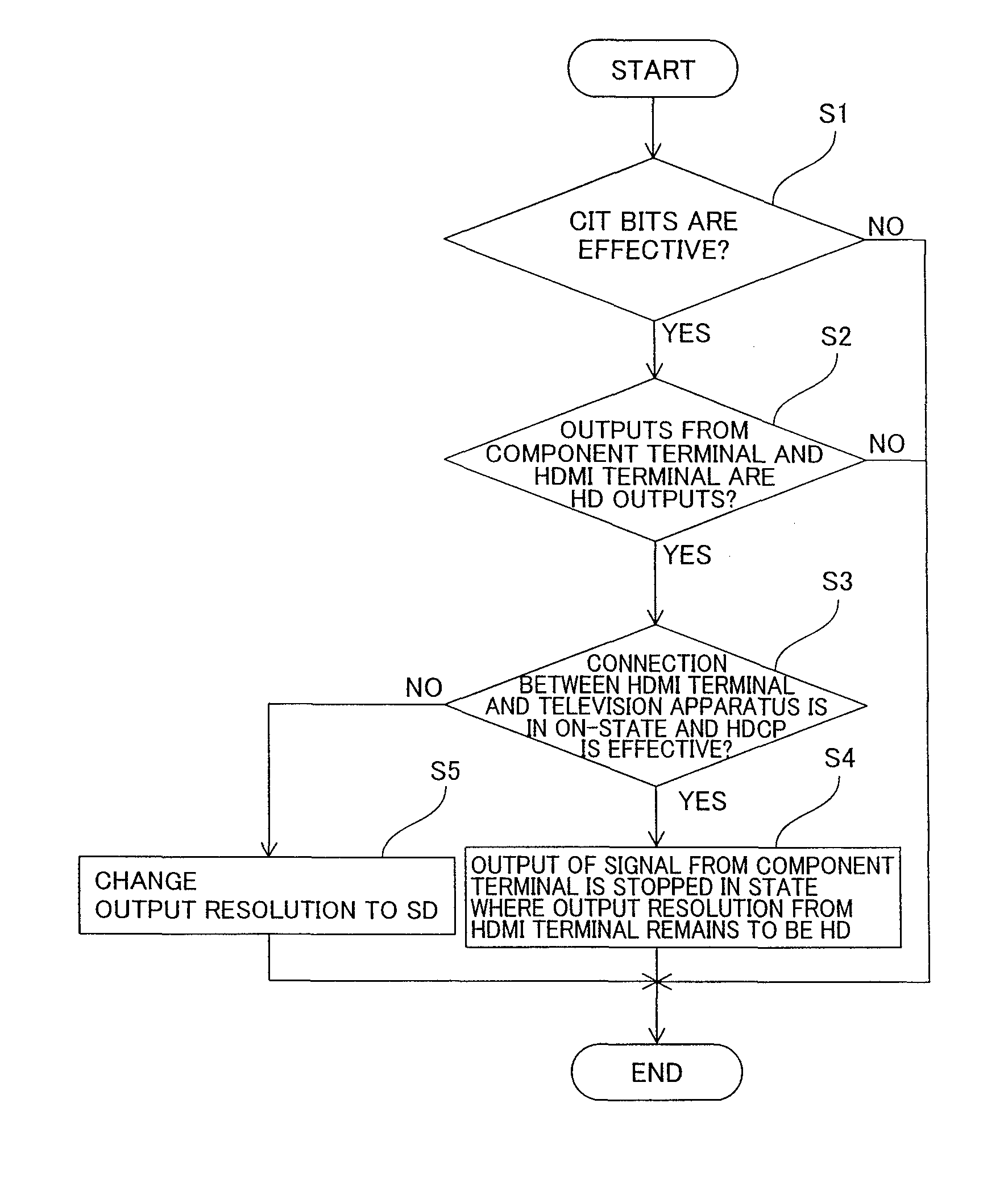
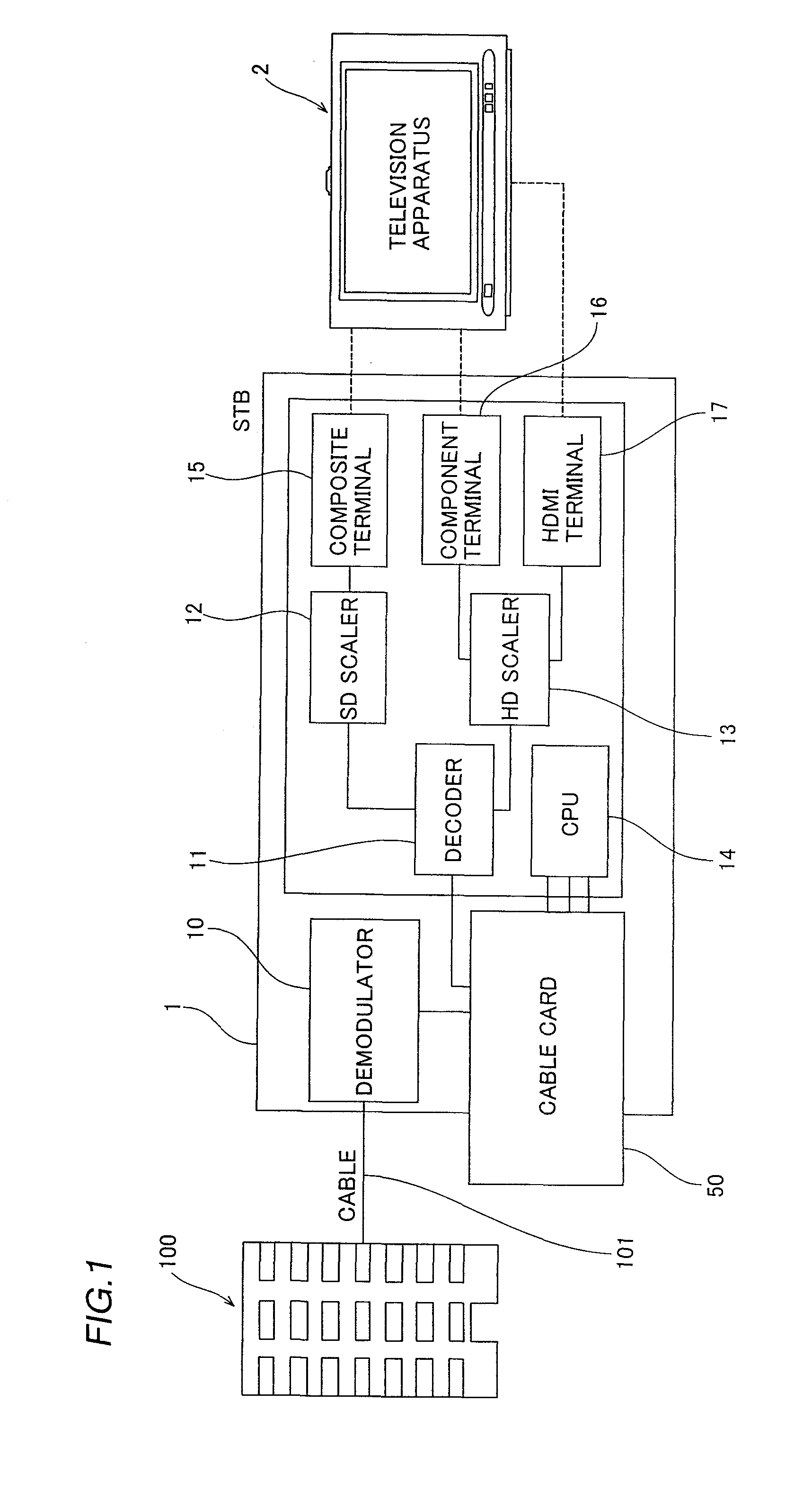
[0037]First, the structure of an STB (Set Top Box) 1 according to an embodiment of the present invention is described with reference to FIGS. 1 to 4. This embodiment of the present invention is applied to the STB 1 employed as an exemplary “video signal processing apparatus” of the present invention.

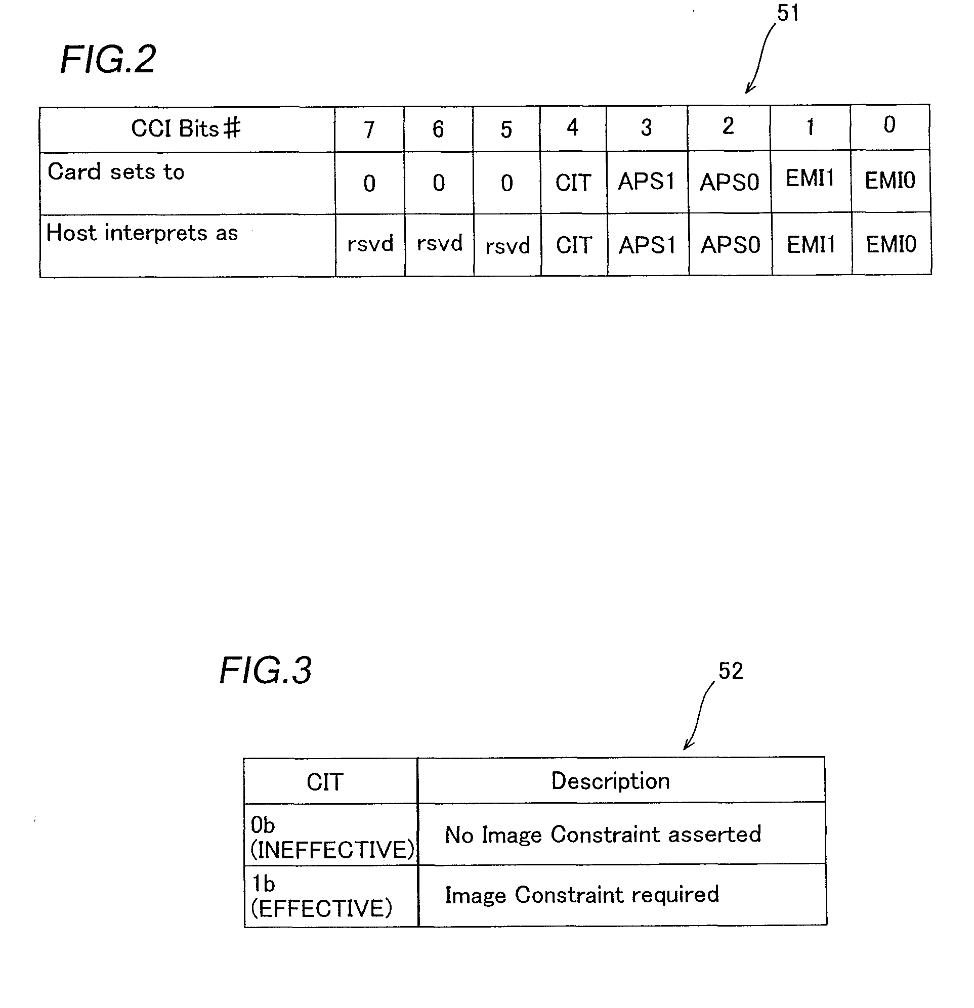
[0038]The STB 1 is an apparatus receiving a broadcast signal transmitted from a cable television station 100 through a cable 101 and outputting a video signal generated on the basis of the received broadcast signal to a television apparatus 2 or the like, as shown in FIG. 1. The television apparatus 2 is an example of the “display” in the present invention. The STB 1 is configured such that a cable card 50 assigned by a cable television station 100 company can be inserted. This cable card 50 has a function of releasing a cipher included in a signal called CCI bits (see Table 51 in FIG. 2) include...


PUM


Abstract

This video signal processing apparatus includes a first resolution conversion portion, a first analog video output portion, a digital video output portion and a control portion. The control portion is so formed as to make the first resolution conversion portion convert a video signal to a digital video signal of high definition and make the digital video output portion output the digital video signal of the high definition when recognizing that connection between the digital video output portion and a display is in an on-state, also in a case where a broadcast signal includes a signal for restricting output of the video signal of the high definition.

Description

BACKGROUND OF THE INVENTION [0001]1. Field of the Invention[0002]The present invention relates to a video signal processing apparatus and a set top box, and more particularly, it relates to a video signal processing apparatus and a set top box comprising a resolution conversion portion capable of converting a resolution.[0003]2. Description of the Background Art[0004]An STB (Set Top Box) and a video signal processing apparatus such as a DVD player, comprising a resolution conversion portion capable of converting a resolution are known in general, as disclosed in Japanese Patent Laying-Open No. 2006-319502, for example.[0005]The aforementioned Japanese Patent Laying-Open No. 2006-319502 discloses a recording and reproducing unit (video signal processing apparatus) comprising a picture frame converting unit (resolution conversion portion) capable of converting a resolution, an analog video output terminal capable of outputting a converted analog video signal to a television receiver (...

Claims


Application Information

Patent Timeline
IPC IPC(8): H04N7/16H04N7/01H04N7/173H04N21/4402H04N21/4623
CPCH04N21/4122H04N21/442H04N21/440263
Inventor KAWAI, MASANORI
Owner FUNAI ELECTRIC CO LTD
Why Eureka
Try Eureka