Building venting system

Inactive Publication Date: 2010-12-30
MONTGOMERY IDA
3 Cites 6 Cited by

AI-Extracted Technical Summary

Problems solved by technology

These differences may cause moisture accumulation and heat buildup in the enclosed spaces.
Provision of such venting typically requires visible penetrations of roofs or at...

Abstract

A system for venting enclosed spaces between a roof and an attic space of a building may comprise an opening in a roof deck; wherein exterior roofing material overlies the roof deck and completely overlies the opening; wherein the roofing material comprises roof material segments; and wherein the roof material segments are in spaces between segments through which air flow can pass.

Application Domain

Building roofsLighting and heating apparatus +7

Technology Topic

Closed spaceAttic +1

Image

  • Building venting system
  • Building venting system
  • Building venting system

Examples

  • Experimental program(1)

Example

[0015]The following detailed description is of the best currently contemplated modes of carrying out exemplary embodiments of the invention. The description is not to be taken in a limiting sense, but is made merely for the purpose of illustrating the general principles of the invention, since the scope of the invention is best defined by the appended claims.
[0016]Various inventive features are described below that can each be used independently of one another or in combination with other features.
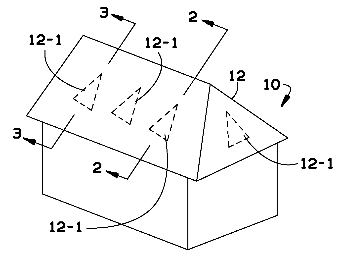
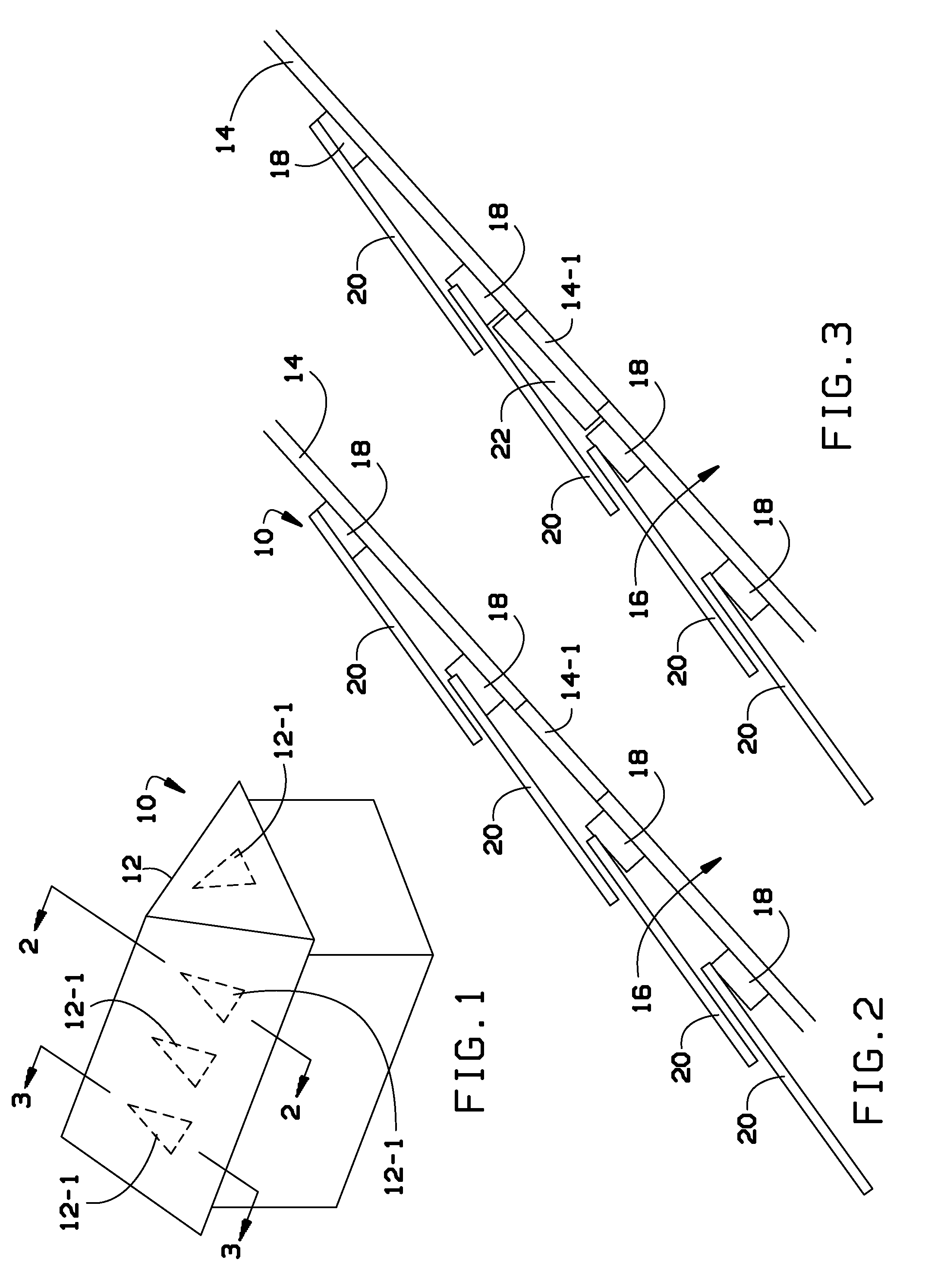
[0017]Broadly, an exemplary embodiment of the invention may comprise a system of venting enclosed spaces of a building through an opening in sheathing or the roof deck of the building over which segmented exterior building covering material may be placed. The segmented exterior building covering material may be elevated from a surface of the sheathing or roof deck so that air may flow through the opening and through openings between segments of the exterior building covering material.
[0018]Referring now to FIG. 1, a building 10 is illustrated in simplified form. In an exemplary embodiment of the invention a roof 12 may be provided with venting. The venting may be invisible to an observer outside of the building 10. For purposes of illustration, areas of venting may be identified by the numeral 12-1.
[0019]Referring now to FIG. 2 a partial cross sectional view of the roof 12 may illustrate an exemplary embodiment of a venting system in accordance with the invention. A roof deck 14 may have an opening 14-1 therethrough. The roof deck 14 may enclose an attic or other enclosed space 16 above a ceiling (not shown) of the building 10. Battens or supports 18 may be attached to the roof deck 14. Segments 20 of exterior roof material or exterior building covering material may be attached to the supports 18. The segments 20 may be materials such as concrete or clay tile or segments of metal roofing. The segments 20 may be installed so that spaces between individuals ones of the segments 20 may permit air flow. In the exemplary embodiment of FIG. 2, air may flow through he opening 14-1 and past the segments 20 so that humid and/or heated air may be vented from the enclosed space 16.
[0020]In another embodiment of the present invention, a vent assembly 22 may be placed over the opening 14-1 as shown in FIG. 3. The vent assembly 22 may have a thickness less than a thickness of the supports 18. Thus the segments 20 may overlie the vent assembly 22 and the vent assembly may be invisible from an exterior of the building 10.
[0021]Referring now to FIGS. 4A and 4B, an exemplary embodiment of one of the vent assemblies 22 may be seen in detail. The vent assembly may comprise a frame 22-1 and a screened opening 22-2. FIG. 4A may illustrate a top side 23 (i.e., a side of the vent assembly 22 which when installed would be facing away from the sheathing or roof deck 14 of FIG. 3. FIG. 4B may illustrate a bottom side 24 (i.e., a side of the vent assembly 22 which when installed would be facing toward the sheathing or roof deck 14 of FIG. 3). A main moisture diverter 22-3 may be attached to the top side 23. Secondary moisture diverters 22-4 may also be attached to the top side 23. The moisture diverters 22-3 and 22-4 may prevent incursion of moisture or rain water into the enclosed space 16 of FIG. 3.
[0022]Referring now to FIG. 4C, the bottom side 24 of the vent assembly 22 may be seen in detail. In FIG. 4C, an exemplary embodiment of an installation arrangement of the vent assembly 22 is shown. The vent assembly 22 may be positioned adjacent to two of the battens or supports 18. The vent assembly may have a rectangular portion 22-5 with a length L that is about the same as spacing between the supports 18. The vent assembly may be provided with nailing holes 22-6 which are spaced apart a width W that corresponds to spacing between rafters (not shown) that support the roof deck 16 of FIG. 3. An adhesive strip 22-7 may be applied to the bottom side 24 so that incursion of rain water or moisture incursion may be precluded between the bottom side 24 and the deck 14.
[0023]Referring now to FIGS. 5A through 5E, there is illustrated an exemplary embodiment of a vent assembly 30. The vent assembly 30 may have moisture diverters 30-1 which may preclude moisture or rainwater incursion. The vent assemblies 30 may have a chevron configuration with triangularly shaped openings 30-2. In the case of the vent assembly 30, the triangularly shaped opening 30-2 may be configured so that a single clay tile used as outer roofing material may overlie the entire opening 30-2.
[0024]The vent assemblies 22 and/or 30 may be constructed from sheet metal or alternatively they may be constructed as molded plastic units. When used on roof decks, the vent assemblies 22 and/or 30 may have an overall thickness of about ¾ inch so that they do not protrude above the supports 18.
[0025]While the vent assemblies have been described herein as roof vents, it may be noted the vent assemblies 22 and/or 30 may be employed to provide venting through vertical walls of buildings. The vent assemblies may also be used in conjunction with gable end vents, ridge vents, and soffit vents or dormer vents. For example, if a building has a large attic, some gable ends vents may be used and these gable ends vents may be supplemented with roof venting in accordance with the present invention and building code requirement.
[0026]It should be understood, of course, that the foregoing relates to exemplary embodiments of the invention and that modifications may be made without departing from the spirit and scope of the invention as set forth in the following claims.

PUM

no PUM

Description & Claims & Application Information

We can also present the details of the Description, Claims and Application information to help users get a comprehensive understanding of the technical details of the patent, such as background art, summary of invention, brief description of drawings, description of embodiments, and other original content. On the other hand, users can also determine the specific scope of protection of the technology through the list of claims; as well as understand the changes in the life cycle of the technology with the presentation of the patent timeline. Login to view more.
Why Eureka
Try Eureka