Sealed battery and method for manufacturing the same

a technology of sealed batteries and closed spaces, which is applied in the direction of secondary cell servicing/maintenance, sustainable manufacturing/processing, cell components, etc., can solve the problems of increasing the pressure in the closed space of the current interruption mechanism at the side corresponding to the outside of the battery, and accelerating the development of evs and hevs, etc., to achieve the effect of high reliability

Active Publication Date: 2010-09-16
SANYO ELECTRIC CO LTD
View PDF6 Cites 69 Cited by
  • Summary
  • Abstract
  • Description
  • Claims
  • Application Information

AI Technical Summary

Benefits of technology

[0007]The present invention is based on the above described experimental results. An advantage of some aspects of the invention is to provide a sealed battery with high reliability including a connecting terminal having a structure in which an electrolyte or washing solution hardly enters a current interruption mechanism during the manufacture and a method for manufacturing the same.
[0009]The through-hole formed in the connecting terminal is for examining leakage of the current interruption mechanism in the assembly process, but during pouring an electrolyte or washing, the electrolyte or washing water may enter the through-hole of the connecting terminal. When the electrolyte or washing water enters the through-hole, the current interruption mechanism may corrode, which may cause a malfunction. In the sealed battery according to the aspect of the invention, the through-hole is sealed with the terminal stopper made of an elastic member, and moreover, the space enclosed with the through-hole and current interruption mechanism is made a closed space, so that the electrolyte or washing water does not enter the through-hole. Thus, the malfunction due to the corrosion of the current interruption mechanism does not occur, and consequently, a sealed battery with high reliability can be obtained.
[0018]In the method for manufacturing a sealed battery according to the aspect of the invention, because the air leakage between the connecting terminal and current interruption mechanism is examined in the second step, batteries with welding defects can be screened out in the assembly process, and moreover, because the terminal stopper made of an elastic member is inserted into the through-hole in the third step, entering an electrolyte into the through-hole can be inhibited during subsequent electrolyte pouring and water washing performed as necessary. Thus, according to the method for manufacturing a sealed battery according to the aspect of the invention, defectives are screened out in the process and a malfunction due to the corrosion of the current interruption mechanism does not occur, and consequently, a sealed battery with high reliability can be manufactured. Here, examples of the gas used for examining air leakage include an inert gas such as nitrogen (N2) gas and dry air.
[0020]The terminal stopper may fall off by vibration and the like because of being composed of an elastic member. In the method for manufacturing a sealed battery according to the aspect of the invention, the terminal stopper composed of the elastic member and metal plate is used, and moreover, the metal plate is welded to the connecting terminal, so that the through-hole can be sealed more tightly. When the metal plate is welded, the welding is easier to perform by the laser welding method.
[0022]According to the method for manufacturing a sealed battery according to the aspect of the invention, because the current interruption mechanism including the sealing tab, inversion plate, and collector having the breaking portion is used, the inversion plate is attached to the sealing tab, and thereafter, the air leakage between the sealing tab and inversion plate is examined. Therefore, the battery with welding defects can be screened out more exactly in the assembly process, and consequently, a sealed battery with higher reliability can be manufactured.
[0024]According to the method for manufacturing a sealed battery according to the aspect of the invention, because the breaking portion of the collector is attached to the inversion plate, and thereafter, the air leakage between the inversion plate and the breaking portion of the collector is examined again, the battery with welding defects can be screened out more exactly in the assembly process. As a result of this, a sealed battery with higher reliability can be manufactured.

Problems solved by technology

In addition, a recent sudden rise in the price of fossil fuels has accelerated the development of EVs and HEVs.
That is, even when the pressure in the outer can is increased for some reason, because the pressure of gas generated in the battery under abnormal conditions is very high, the pressure in the closed space on the current interruption mechanism at the side corresponding to the outside of the battery seldom simultaneously increases equally.
When the electrolyte or washing water enters the through-hole, the current interruption mechanism may corrode, which may cause a malfunction.

Method used


Image

  • Sealed battery and method for manufacturing the same
  • Sealed battery and method for manufacturing the same
  • Sealed battery and method for manufacturing the same

Examples


Embodiment Construction

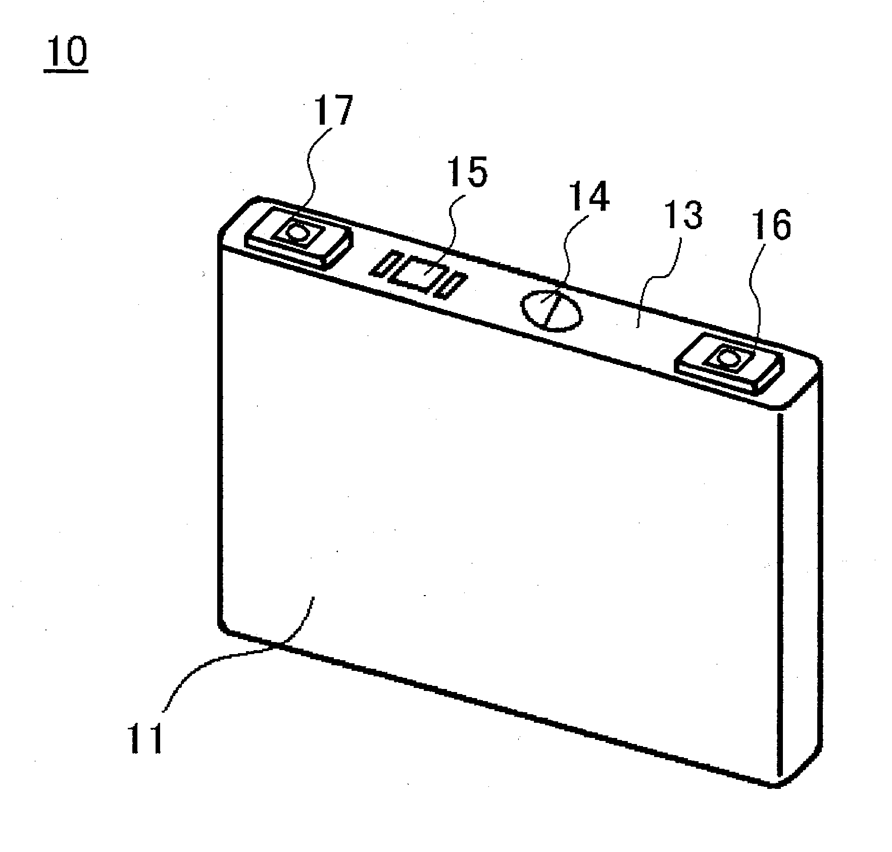
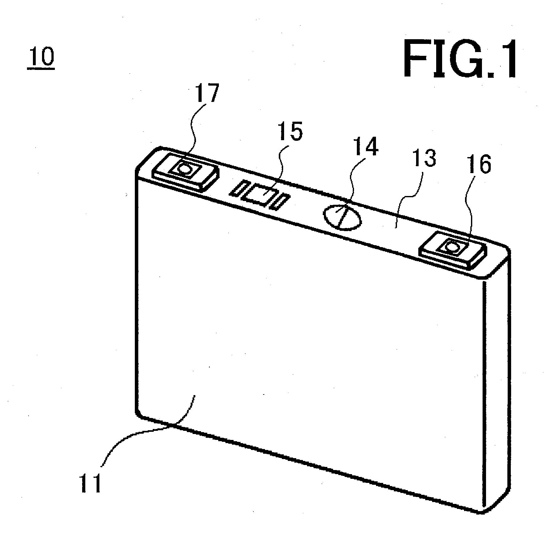
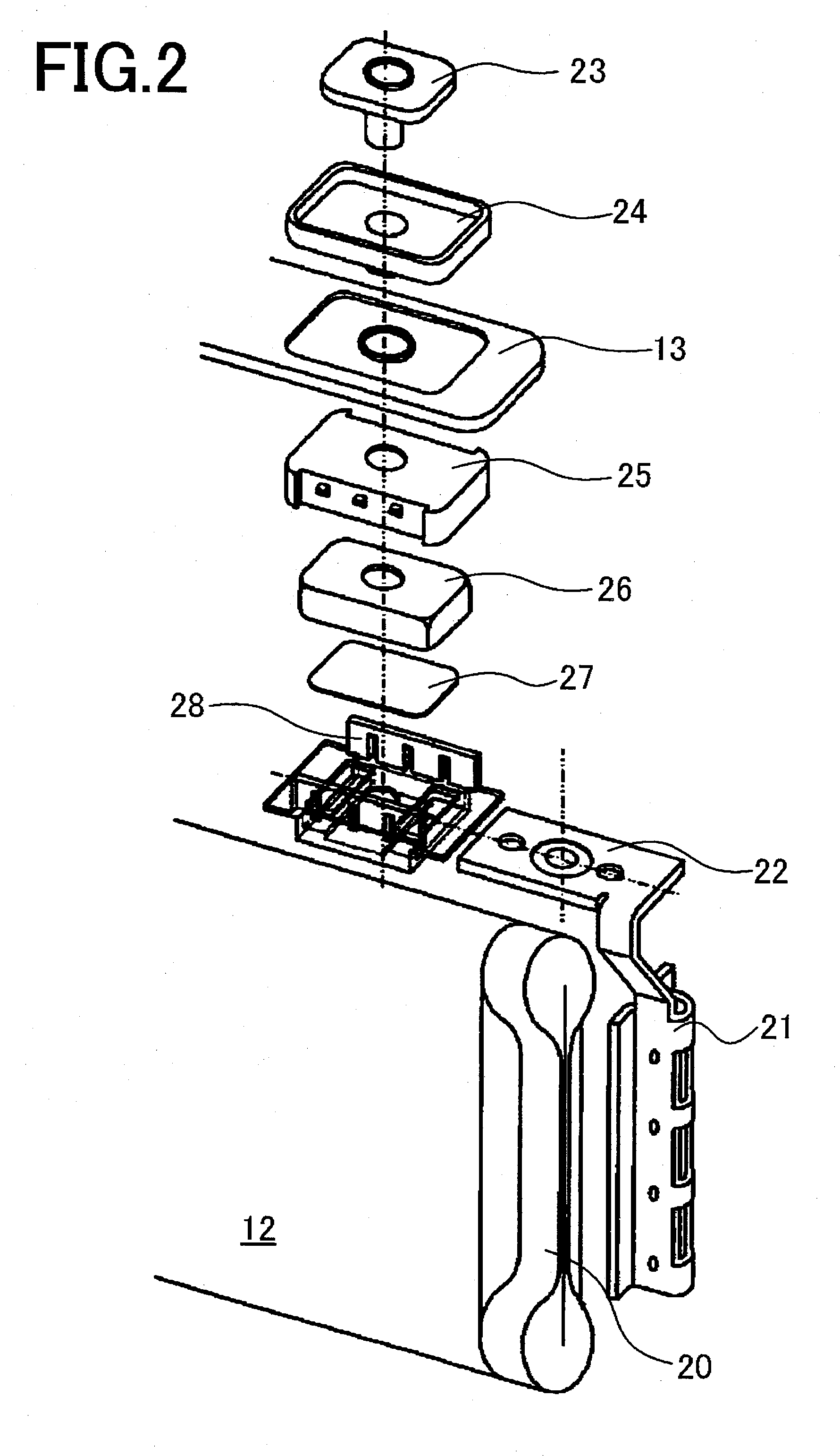
[0031]Hereinafter, exemplary embodiments of the invention will be described in detail with drawings, and, in the description below, the positive electrode external terminal of the positive electrode plate will be exemplified. In a sealed battery 10 of the present embodiment, as shown in FIG. 1 and FIG. 2, a positive electrode plate and negative electrode plate are rolled and pressed into a flat shape to form a rolled electrode assembly 12, the rolled electrode assembly 12 is stored in an outer can 11 in a transversal direction with respect to the axis direction of the outer can 11, and a mouth of the outer can 11 is sealed with a sealing plate 13. Furthermore, to the sealing plate 13, a gas exhaust valve 14, electrolyte pouring hole (not shown in the drawings) and sealing member 15 for the electrolyte pouring hole are installed. The gas exhaust valve 14 opens when the gas pressure is higher than the working pressure of a current interruption mechanism.

[0032]In addition, to the seali...


PUM

PropertyMeasurementUnit
pressureaaaaaaaaaa
diameteraaaaaaaaaa
lengthaaaaaaaaaa

Abstract

The sealed battery includes a sealing plate 13 sealing a mouth of an outer can, an external terminal 16 attached to the sealing plate 13 and having a connecting terminal 23, and a current interruption mechanism 18 interrupting current in response to pressure increase in the outer can that is installed in a conductive pathway electrically connecting the connecting terminal 23 and an electrode assembly. In the connecting terminal 23, a through-hole 23b continuing to the space on the current interruption mechanism 18 at the side corresponding to the outside of the battery is formed. The through-hole 23b is sealed with a terminal stopper 30 made of an elastic member so as to form a closed space between the terminal stopper 30 and current interruption mechanism 18. An electrolyte or washing solution hardly enters the current interruption mechanism during the manufacture can be provided.

Description

TECHNICAL FIELD[0001]The present invention relates to a sealed battery such as a nonaqueous electrolyte secondary battery and nickel-hydrogen secondary battery and, in particular, relates to a sealed battery with high reliability which includes a current interruption mechanism inside and a connecting terminal having a structure in which an electrolyte or washing solution hardly enters the current interruption mechanism during the manufacture, and a method for manufacturing the same.BACKGROUND ART[0002]As power supplies for driving portable electronic equipment such as cell phones, portable personal computers, and portable music players, alkaline secondary batteries represented by a nickel hydrogen battery and nonaqueous electrolyte secondary batteries represented by a lithium ion battery are widely used. Furthermore, exhaust controls of carbon dioxide gas and the like are being tightened up in view of the recent moves to protect the environment. Thus, in the car industry, not only a...

Claims


Application Information

Patent Timeline
Patent Type & Authority Applications(United States)
IPC IPC(8): H01M2/08H01M2/00H01M50/176H01M50/184H01M50/186H01M50/191H01M50/197H01M50/198H01M50/55H01M50/553H01M50/566H01M50/574H01M50/627
CPCH01M2/021Y10T29/4911H01M2/08H01M2/34H01M2/36H01M10/05H01M10/12H01M10/345H01M10/42H01M10/425Y02E60/124Y02E60/126Y02T10/7016H01M10/04Y10T29/49108H01M2/0217Y02P70/50Y02E60/10H01M50/103H01M10/058H01M50/186H01M50/198H01M50/566H01M50/184H01M50/55H01M50/553H01M50/574H01M50/176H01M50/627H01M50/191H01M50/197H01M50/543H01M50/20H01M50/60H01M10/48Y02T10/70
Inventor NANSAKA, KENJIYAMAUCHI, YASUHIRONOHMA, TOSHIYUKI
Owner SANYO ELECTRIC CO LTD
Why Eureka
Try Eureka