
Position detector, position detecting circuit and position detecting method

a position detector and position detecting technology, applied in the direction of instruments, computing, electric digital data processing, etc., can solve the problems of detector itself malfunctioning, the position of the finger cannot be properly detected, and the differential amplifier cannot cancel the noise, etc., to achieve high precision and usefulness, simple configuration, and effective cancellation of the noise

Active Publication Date: 2010-12-30
WACOM CO LTD
View PDF7 Cites 21 Cited by
  • Summary
  • Abstract
  • Description
  • Claims
  • Application Information

AI Technical Summary

Benefits of technology

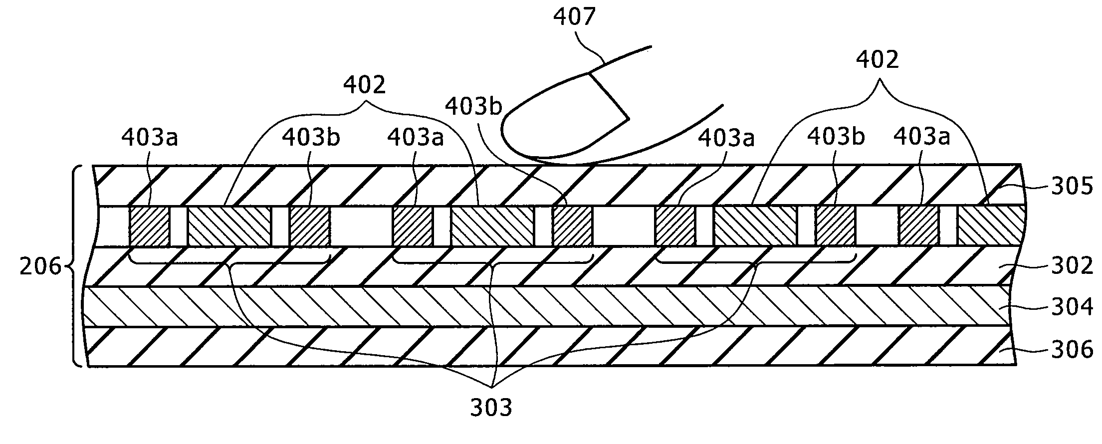
[0018]The present invention has been made in order to solve the problems described above, and according to one aspect the present invention provides a highly precise and useful position detector which is capable of effectively canceling noises immixed thereto through the human body with a simple configuration, a position detecting circuit, and a position detecting method.
[0020]Each of the reception electrode lines composing the reception electrode is divided into three parts (three electrode lines). In this case, the central electrode line is connected to the plus side input terminal of the differential amplifier, and the electrode lines located on the both end sides of the central electrode line, respectively, are connected to the minus side input terminal of the differential amplifier. As a result, the noises immixed from the finger of the human body to the position detector can be effectively canceled by the differential amplifier.
[0023]As set forth hereinabove, according to the present invention, it is possible to provide a highly precise and useful position detector which is capable of effectively canceling the noises immixed thereto through the human body with a simple configuration, the position detecting circuit, and the position detecting method.

Problems solved by technology

The case of the noises immixed only to one of the two electrode lines through the human body causes a problem that, with the structure of the electrode lines on the reception side as described above, such noises cannot be canceled by the differential amplifier.
As a result, there is encountered such a problem that the position of the finger cannot be properly detected, or the position detector itself malfunctions.

Method used


Image

  • Position detector, position detecting circuit and position detecting method
  • Position detector, position detecting circuit and position detecting method
  • Position detector, position detecting circuit and position detecting method

Examples


Embodiment Construction

[0035]The preferred embodiments of the present invention will be described in detail hereinafter with reference to the accompanying drawings.

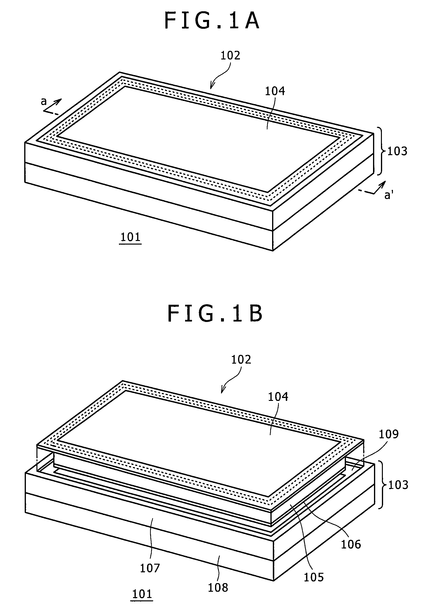
[0036]FIGS. 1A and 1B are a perspective view and an exploded perspective view, respectively, showing an external appearance of an input device with a display function including an electrostatic capacitance type position detector according to an embodiment of the present invention.

[0037]The input device 101 with a display function is a device in which a Liquid Crystal Display (LCD) device and a position detector using an electrostatic capacitance system are combined to be integrated with each other.

[0038]In the input device 101 with a display function, a liquid crystal module portion 102 is accommodated in a case portion 103. A surface of the liquid crystal module portion 102 and a peripheral portion of the case portion 103 are formed at the same height so that a user can carry out natural drawing when he / she carries out a desired drawing manipu...

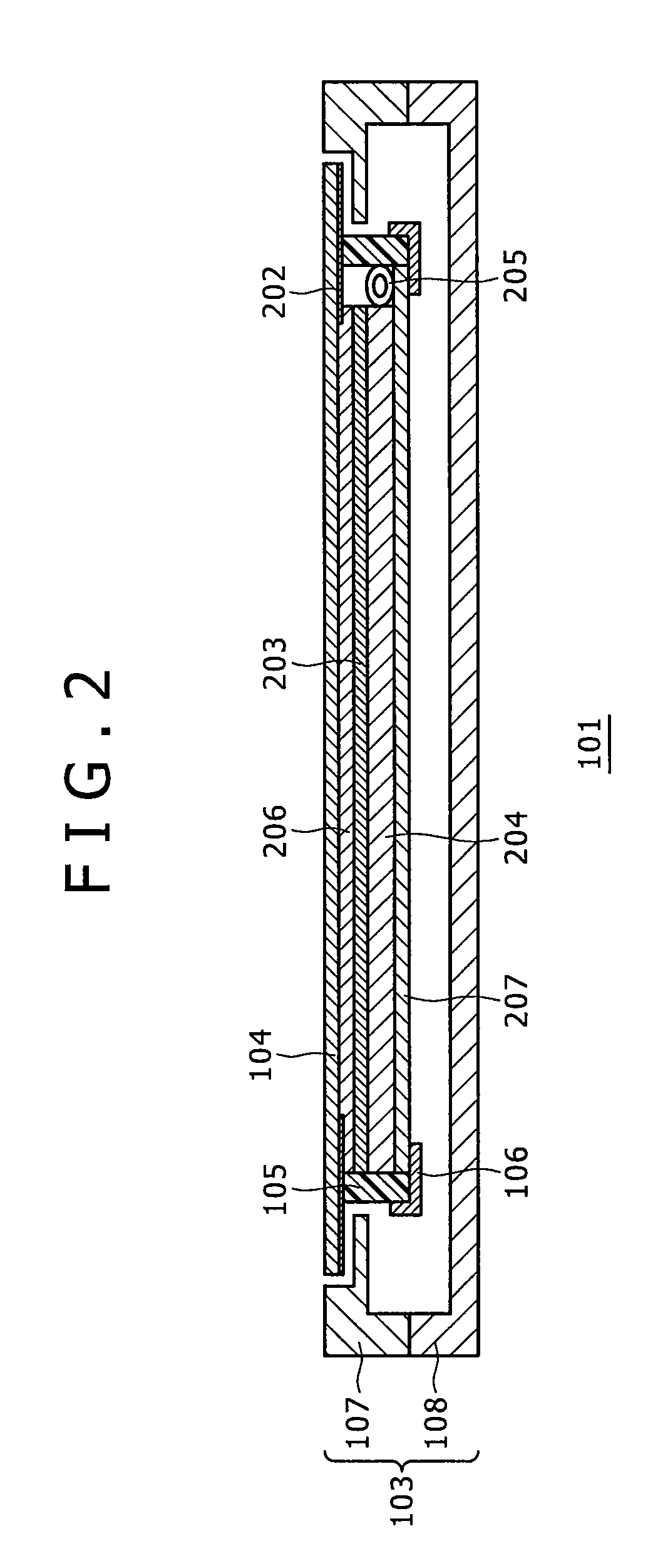

PUM


Abstract

A position detector is provided including: a transmission signal supplying circuit for supplying a transmission signal to a plurality of conductors disposed in a first direction; a first conductor selecting circuit for supplying the transmission signal outputted from the transmission signal supplying circuit to a predetermined conductor(s) of the plurality of conductors disposed in the first direction; a differentially amplifying circuit for differentially amplifying signals inputted thereto through its first and second input terminals, respectively, and outputting a resulting signal; and a second conductor selecting circuit for selecting a plurality of conductors including at least three conductors located close to one another in a plurality of conductors disposed in a second direction intersecting with the first direction, supplying signals from the conductors located on both end sides of the plurality of conductors thus selected to the first input terminal, and supplying a signal(s) from the conductor(s) other than the conductors located on both end sides, respectively, to the second input terminal.

Description

CROSS-REFERENCE TO RELATED APPLICATION(S)[0001]The present application claims priority to Japanese Patent Application No. 2009-154204, filed Jun. 29, 2009, the entire content of which is incorporated herein by reference.BACKGROUND OF THE INVENTION[0002]1. Field of the Invention[0003]The present invention relates to a technique suitable for being applied to a position detector, a position detecting circuit, and a position detecting method.[0004]More particularly, the present invention relates to a technique for reducing noises immixed from a position detection planar surface in a position detector using an electrostatic capacitance system, thereby enhancing a detection precision for a finger of the human body.[0005]2. Description of the Related Art[0006]There are known various kinds of input devices each of which gives position information to a computer. Of these input devices, there is known a two-dimensional position information input device (hereinafter referred to as “a position ...

Claims


Application Information

Patent Timeline
Patent Type & Authority Applications(United States)
IPC IPC(8): G06F3/041
CPCG02F1/13338G06F3/044G06F3/0412G06F3/0445G06F3/0446
Inventor MATSUBARA, MASAKI
Owner WACOM CO LTD
Learn More