Heat sink assembly with temperature display

a technology of temperature display and heat sink, which is applied in the direction of heat measurement, electric apparatus casing/cabinet/drawer, instruments, etc., can solve the problems of inconvenient temperature detection and high cost of extra detecting devices

Inactive Publication Date: 2010-12-30
HONG FU JIN PRECISION IND (SHENZHEN) CO LTD +1
View PDF8 Cites 12 Cited by
  • Summary
  • Abstract
  • Description
  • Claims
  • Application Information

AI Technical Summary

Problems solved by technology

However, the extra detecting device may be expensive and inconvenient for detecting temperatures of these electronic devices.

Method used


Image

  • Heat sink assembly with temperature display
  • Heat sink assembly with temperature display
  • Heat sink assembly with temperature display

Examples


Embodiment Construction

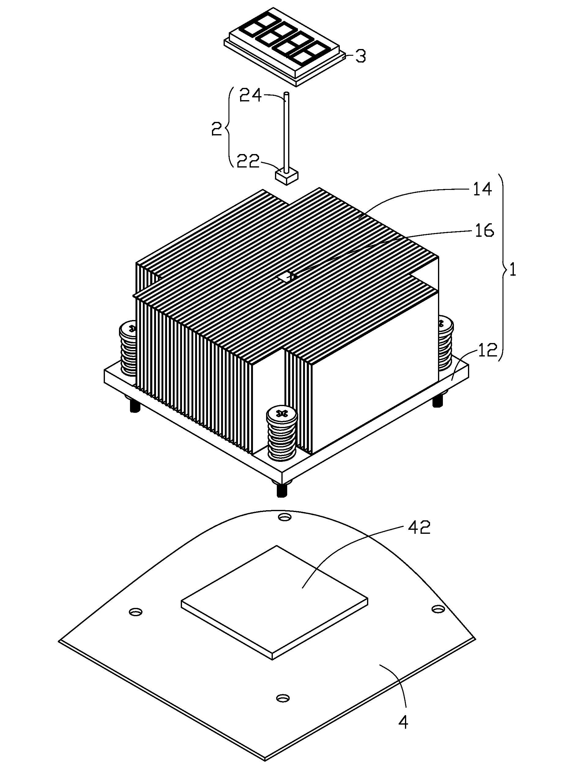
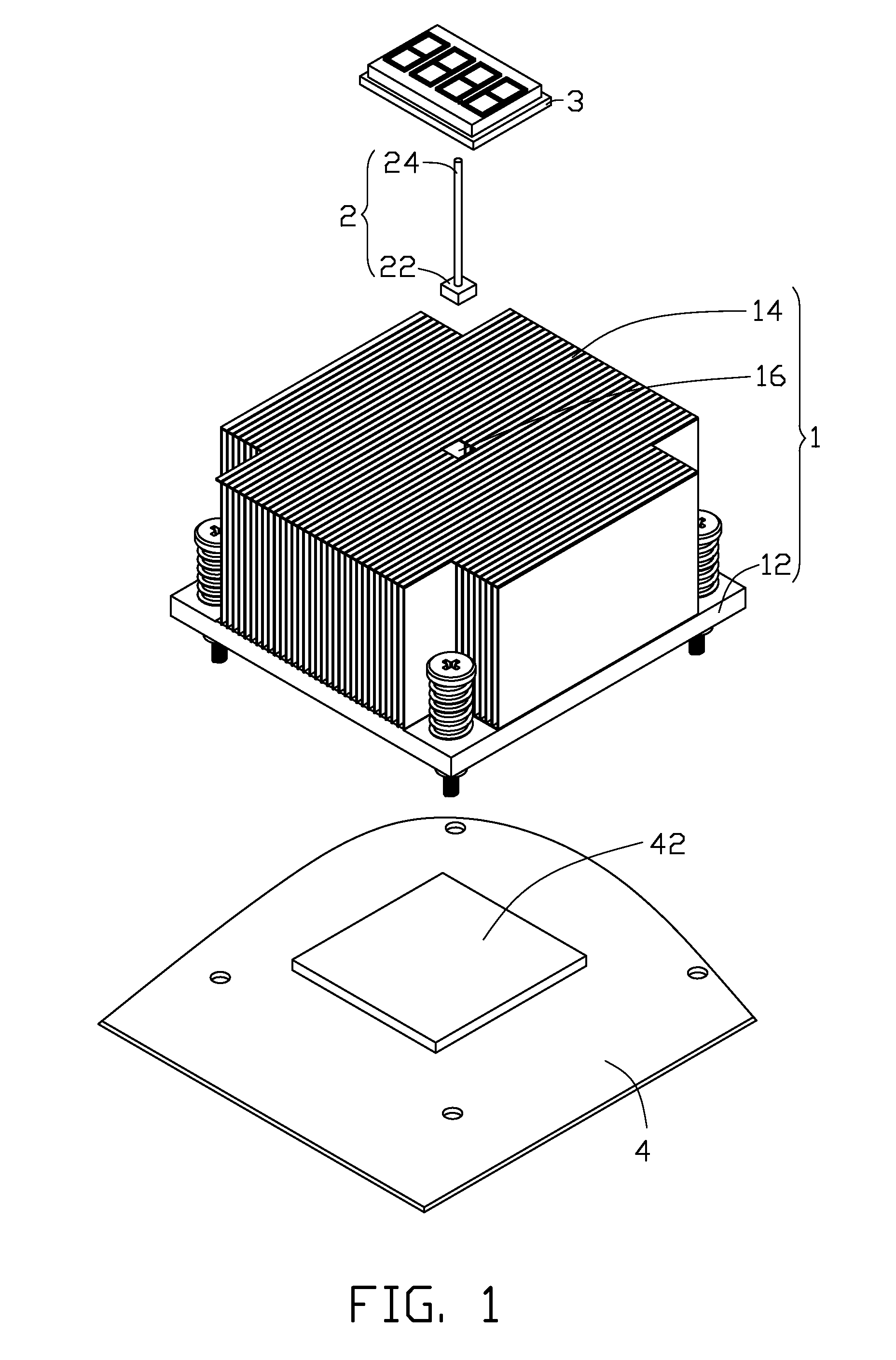
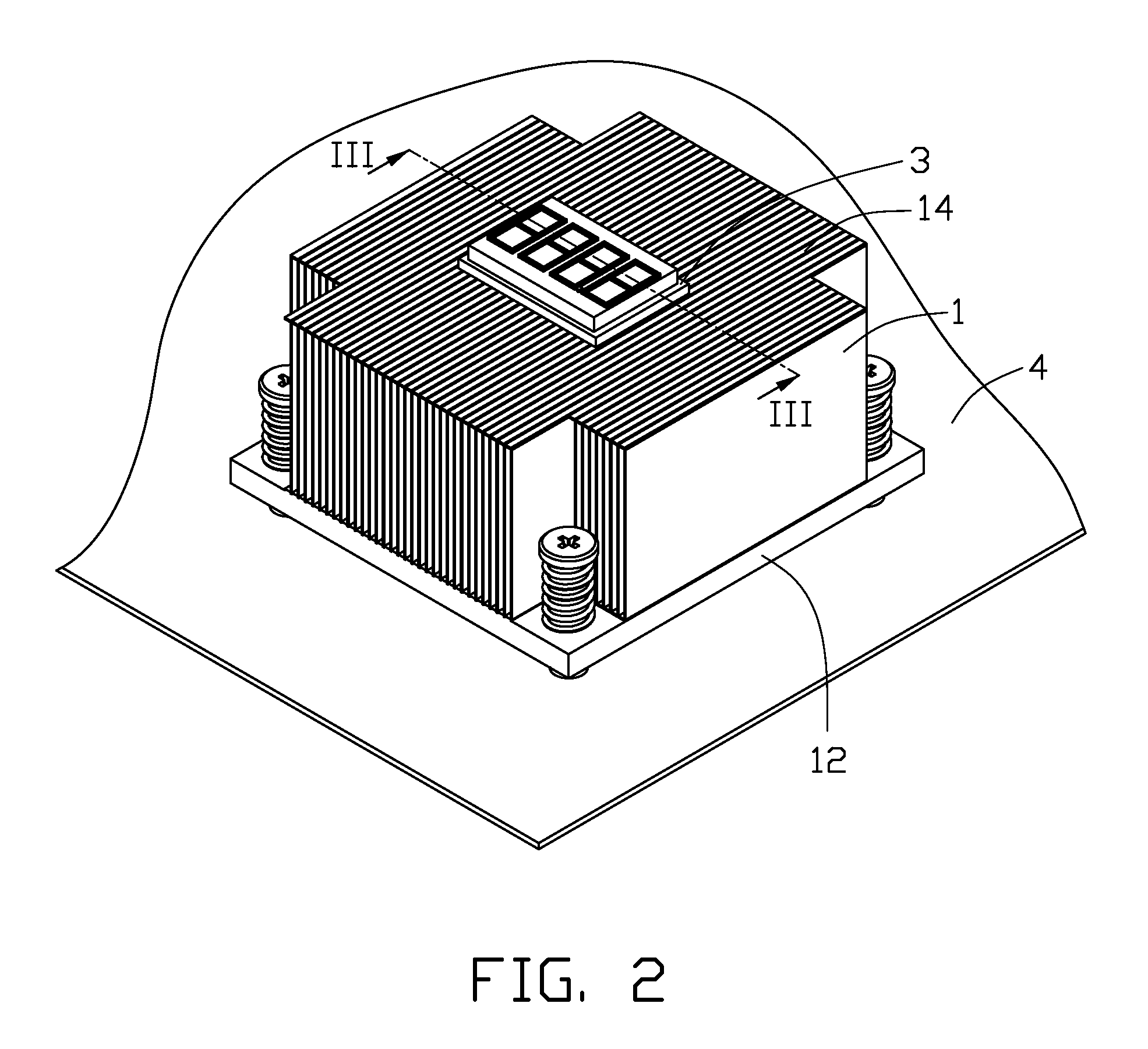
[0008]Referring to FIGS. 1 to 3, an exemplary embodiment of a heat sink assembly is used to dissipate heat and detect temperature of a chip 42 of a circuit board 4. The heat sink assembly includes a heat sink 1, a temperature collecting module 2, and a display module 3.

[0009]The heat sink 1 includes a conductive board 12 and a plurality of parallel fins 14 vertically extending up from the conductive board 12. A hole 16 is longitudinally defined in a center of the plurality of parallel fins 14 and through the conductive board 12.

[0010]In one embodiment, the temperature collecting module 2 is a thermocouple sensor and includes a sensing portion 22 and a signal transferring portion 24. The sensing portion 22 is used to sense temperature of the chip 42 and generate corresponding analog signals. The signal transferring portion 24 is connected to the sensing portion 22, to transfer the analog signals to the display module 3. In other embodiments, the temperature collecting module 2 can be...


PUM


Abstract

A heat sink assembly dissipates heat of a chip on a circuit board. A temperature collecting module of the heat sink assembly senses temperature of the chip and generates corresponding analog signals. A display module of the heat sink assembly receives the analog signals and converts the analog signals into digital signals, and then displays the digital signals with temperature unit symbol.

Description

BACKGROUND[0001]1. Technical Field[0002]The present disclosure relates to heat sinks and, particularly, to a heat sink assembly which can display temperature.[0003]2. Description of Related Art[0004]For testing electronic devices, such as central processing units (CPUs), south bridge chips, and north bridge chips, detecting temperatures of these electronic devices is very important for testers to determine whether the electronic devices are OK. Usually, an extra detecting device needs to be prepared for detecting temperatures of the electronic devices. However, the extra detecting device may be expensive and inconvenient for detecting temperatures of these electronic devices.BRIEF DESCRIPTION OF THE DRAWINGS[0005]FIG. 1 is an exploded, isometric view of an exemplary embodiment of a heat sink assembly, together with a circuit board.[0006]FIG. 2 is an assembled, isometric view of the heat sink assembly and the circuit board of FIG. 1.[0007]FIG. 3 is a cross-sectional view of FIG. 2, t...

Claims


Application Information

Patent Timeline
Patent Type & Authority Applications(United States)
IPC IPC(8): H05K7/20
CPCG01K13/00G01K13/10G06F1/20H01L23/34H01L23/4006H01L2924/0002H01L2023/4081H01L2924/00
Inventor MA, XIAO-FENGLIU, LEICHOU, CHIA-SHIN
Owner HONG FU JIN PRECISION IND (SHENZHEN) CO LTD
Why Eureka
Try Eureka