Micro thermal chamber having proximity control temperature management for devices under test

a technology of proximity control and thermal chamber, which is applied in the direction of instruments, manufacturing tools, coatings, etc., can solve the problems of increasing costs, hindering the response time and the use of high wattage, and not allowing for rapid response times for heating and cooling, etc., and achieves the effect of rapid response and low cos

Inactive Publication Date: 2005-10-13
ADVANTEST CORP
View PDF11 Cites 13 Cited by
  • Summary
  • Abstract
  • Description
  • Claims
  • Application Information

AI Technical Summary

Benefits of technology

[0006] It is an aspect of the invention to provide a low cost, robust temperature control unit having rapid response times and which controls a temperature of a device under test by mechanical methods.

Problems solved by technology

However, this solution does not allow for rapid response times for heating and cooling.
As such, the heating unit needs to have a low thermal mass, which increases costs, and hinders the response times and the use of high wattage.
Thus, such liquids are difficult to find, making the use of the liquid impractical.
However, the thermal electric devices are not useful for high power densities and are unreliable in an industrial environment.
As such, the existing solutions to provide temperature control of a DUT are not able to control wide ranges of temperatures, have a fast response time, and also be stable and easy to control during the testing process.

Method used


Image

  • Micro thermal chamber having proximity control temperature management for devices under test
  • Micro thermal chamber having proximity control temperature management for devices under test
  • Micro thermal chamber having proximity control temperature management for devices under test

Examples


Embodiment Construction

[0030] Reference will now be made in detail to the present embodiments of the present invention, examples of which are illustrated in the accompanying drawings, wherein like reference numerals refer to the like elements throughout. The embodiments are described below in order to explain the present invention by referring to the figures.

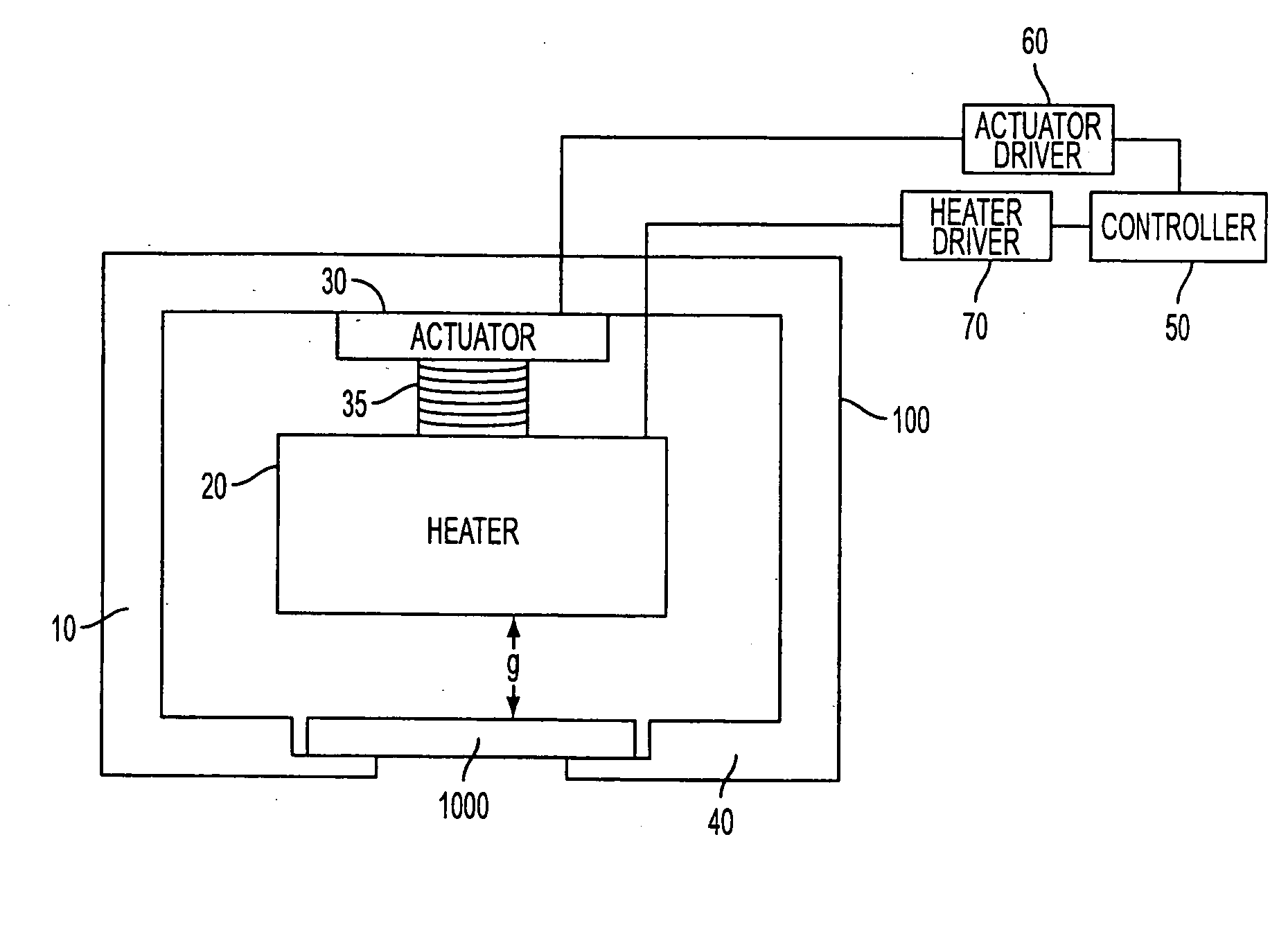
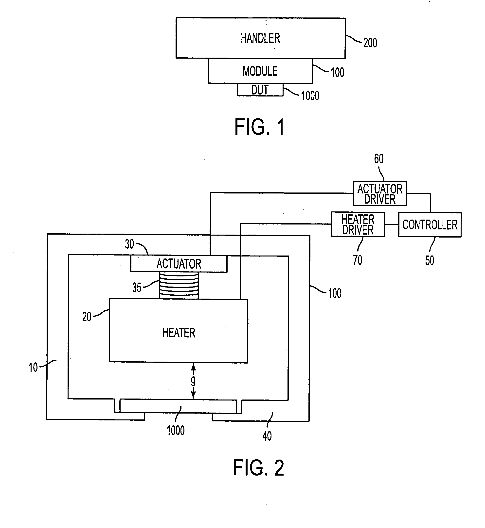
[0031]FIG. 1 schematically shows an embodiment of the invention in which a module 100 is used with a handler 200. As shown in the embodiment of FIG. 2, the module 100 includes a temperature control unit 10 which holds onto a device under test 1000 using an interface 40 to create a space in which the temperature is controlled. Within the space, a heater block 20 is attached to an actuator 30 so as to be movable relative to the device under test 1000 through the action of the actuator 30. As shown, the actuator 30 is a screw type actuator which has threads 35 which allow precise placement of the heater block 20 above the device under test 1000 so as to...


PUM

PropertyMeasurementUnit
temperatureaaaaaaaaaa
thermal resistanceaaaaaaaaaa
temperaturesaaaaaaaaaa

Abstract

A temperature unit to control a temperature of a device under test using a fluid includes a block disposed opposite the device under test and which defines a gap therebetween and through which the fluid passes across the device under test at a gap flow rate, and an actuator which moves the block. By adjusting the gap, the gap flow rate of the fluid flowing over the device under test changes so as to adjust the temperature of the device under test. Additionally, the block can be a heater block which generates heat receivable by the device under test across the gap such that the adjustment of the heater block by the actuator changes a thermal resistance across the gap.

Description

BACKGROUND OF THE INVENTION [0001] During the manufacture of semiconductor devices, the manufactured semiconductor devices are subjected to a battery of tests in order to ensure their suitability for use by the ultimate consumer. This testing process is performed using automated testing equipment (ATE). The ATE system is designed to test the devices (usually referred to as devices under test or DUTs) over a wide variety of conditions. The ATE system generally includes a tester, which performs the test on the devices, and a handler, which introduces the devices to and removes the devices from the tester. During the testing process, it is generally preferred to have the devices kept at a pre-determined temperature since the temperature affects the electrical properties of the devices being tested. Further, in order to test the devices at design temperatures to mimic design and operational conditions of the device, the tester needs to test the devices over a range of temperatures. As s...

Claims


Application Information

Patent Timeline
Patent Type & Authority Applications(United States)
IPC IPC(8): G01R31/319G01R31/28
CPCG01R31/2862G01R31/2877G01R31/31905G01R31/317
Inventor ROY, SHAMBHU N.
Owner ADVANTEST CORP
Why Eureka
Try Eureka