Frame structure, backlight module and display module

a backlight module and frame structure technology, applied in the field of frame structure, backlight module and display module, can solve the problems of tape peeling off, backlight module not being able to provide uniform surface light, backlight module side light leakage, etc., and achieve the effect of reducing light leakag

Active Publication Date: 2010-12-30
AU OPTRONICS CORP
View PDF8 Cites 26 Cited by
  • Summary
  • Abstract
  • Description
  • Claims
  • Application Information

AI Technical Summary

Benefits of technology

[0008]The present invention provides a frame structure which effectively blocks light path to thereby reduce light leakage.
[0009]The present invention provides a backlight module which adopts the above-mentioned frame structure and has better light emitting effects.
[0010]The present invention provides a display module which adopts the above-mentioned backlight module and has better display quality.
[0017]According to the above, the present invention is directed at the design of the fixing structure of the frame structure, wherein by designing the length of the first protrusion to be larger than the overlap length between the stopper portion and the first protrusion and the length of the second protrusion to be larger than the overlap length between the stopper portion and the second protrusion, light path can be effectively blocked by the first protrusion, the second protrusion, and the stopper portion when light emits from the sides, thereby reducing light leakage. In addition, because the frame structure is capable of effectively reduce light leakage, the backlight module adopting the frame structure has better light emitting effect and the display module adopting the backlight module has improved display quality.

Problems solved by technology

The holes are capable of preventing the optical films from shifting on the frame, which, however, also causes light leakage to occur at the sides of the backlight module because of the holes on the frame.
As such, the backlight module is unable to provide uniform surface light.
However, such taping process poses concern of the tape peeling off as well as increases manufacturing cost and time.

Method used


Image

  • Frame structure, backlight module and display module
  • Frame structure, backlight module and display module
  • Frame structure, backlight module and display module

Examples


Embodiment Construction

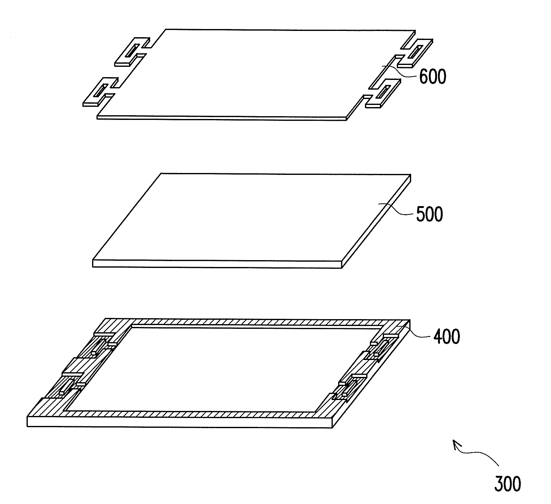
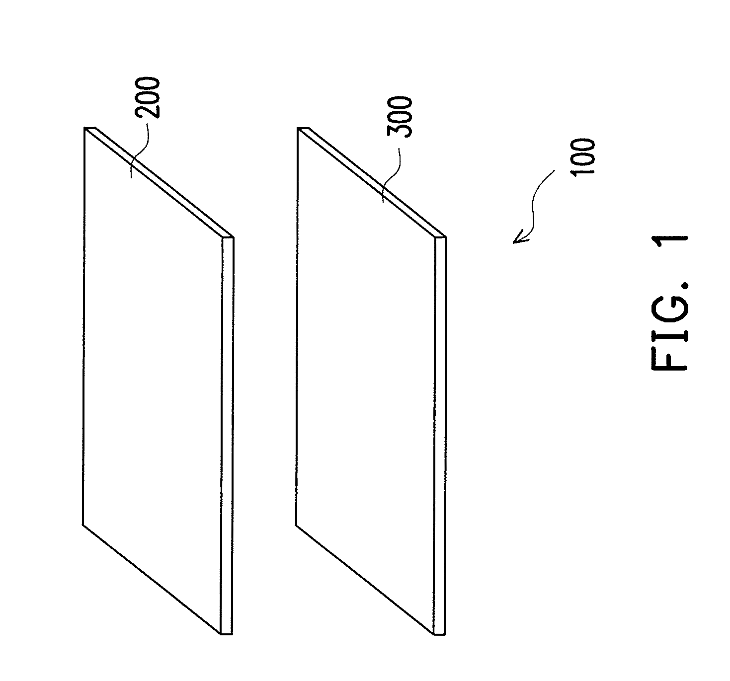
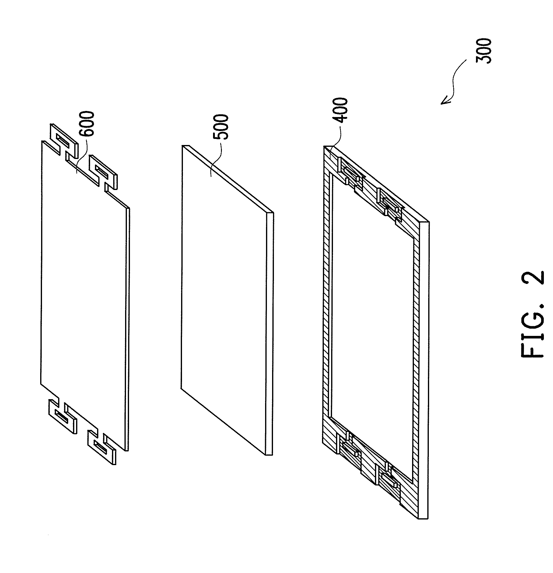
[0025]FIG. 1 is a schematic view of a display module according to an embodiment of the present invention. FIG. 2 is a schematic explosion view of a backlight module of the display module in FIG. 1. FIG. 3 is a schematic assembly view of the backlight module of the display module in FIG. 1. Referring to FIGS. 1, 2, and 3 at the same time, a display module 100 includes a display panel 200 and a backlight module 300, wherein the backlight module 300 is disposed on one side of the display panel 200, for example, under the display panel 200. The backlight module 300 includes a frame structure 400, a light source module 500, and an optical film set 600, wherein the light source module 500 is located in the frame structure 400 for providing brightness to the display panel 200 to display images, the optical film set 600 is located in the frame structure 400 and disposed on the light source module 500. The optical film set 600 may include a plurality of optical films, such as a prism film, d...


PUM

PropertyMeasurementUnit
distanceaaaaaaaaaa
distanceaaaaaaaaaa
distance D1aaaaaaaaaa

Abstract

A frame structure includes a frame body and fixing structures. The frame structure has an inner edge, an end edge and an outer edge. The fixing structures are disposed on two opposite sides of the frame body respectively, wherein each fixing structure includes a first protrusion, a second protrusion and a stopper portion. One end of the first protrusion or one end of the second protrusion connects to the inner and the end edges to form a containing cavity. The stopper portion is located inside the containing cavity and arranged in parallel to the first and the second protrusions. The lengths of the first and the second protrusions are respectively “L1” and “L2”. The overlap length between the stopper portion and the first protrusion is “α,” the overlap length between the stopper portion and the second protrusion is “b,” L1>α≧0, and L2>β≧0.

Description

CROSS-REFERENCE TO RELATED APPLICATION[0001]This application claims the priority benefit of Taiwan application serial no. 98122144, filed on Jun. 30, 2009. The entirety of the above-mentioned patent application is hereby incorporated by reference herein and made a part of specification.BACKGROUND OF THE INVENTION[0002]1. Field of the Invention[0003]The present invention relates to a frame structure, backlight module, and display module, and more particularly to a frame structure capable of reducing light leakage and a backlight module and a display module using the frame structure.[0004]2. Description of Related Art[0005]With the advancement in technology comes the continuing development of display technology. Flat panel displays (FPD) which are light and thin have gradually replaced conventional cathode ray tube (CRT) displays which are heavy and thick. Common FPDs include plasma display panels (PDP) and liquid crystal displays (LCD) which are widely used in personal digital assist...

Claims


Application Information

Patent Timeline
Patent Type & Authority Applications(United States)
IPC IPC(8): G02F1/13357A47G1/06
CPCG02F1/133606G02F2201/54G02F2201/465G02F1/133608
Inventor HUANG, TA-JEN
Owner AU OPTRONICS CORP
Why Eureka
Try Eureka