Isotope production system with separated shielding

a production system and isotope technology, applied in the direction of greenhouse gas reduction, nuclear reactors, therapy, etc., can solve the problems and requiring the removal of original support structures of rooms such as floors, ceilings and walls. , to achieve the effect of reducing the radiation exposure of individuals and being easy to decommissioned

Active Publication Date: 2010-12-30
GENERAL ELECTRIC CO
View PDF22 Cites 47 Cited by
  • Summary
  • Abstract
  • Description
  • Claims
  • Application Information

AI Technical Summary

Problems solved by technology

However, the large amounts of shielding may be costly and too heavy for the rooms where the isotope production system are to be located.
However, designing specific rooms for isotope production systems raises new challenges, especially for pre-existing rooms that were not originally intended for radioisotope production.
Yet another challenge presented by radiation leakage is how to remove the isotope production system when, for example, it is replaced or moved to another location.
In some instances, original support structures of the room, such as floors, ceilings, and walls, must be removed because the support structures have been contaminated by radioactivity.
Such decommissioning and decontaminating procedures can be costly and time-consuming.

Method used


Image

  • Isotope production system with separated shielding
  • Isotope production system with separated shielding
  • Isotope production system with separated shielding

Examples


Embodiment Construction

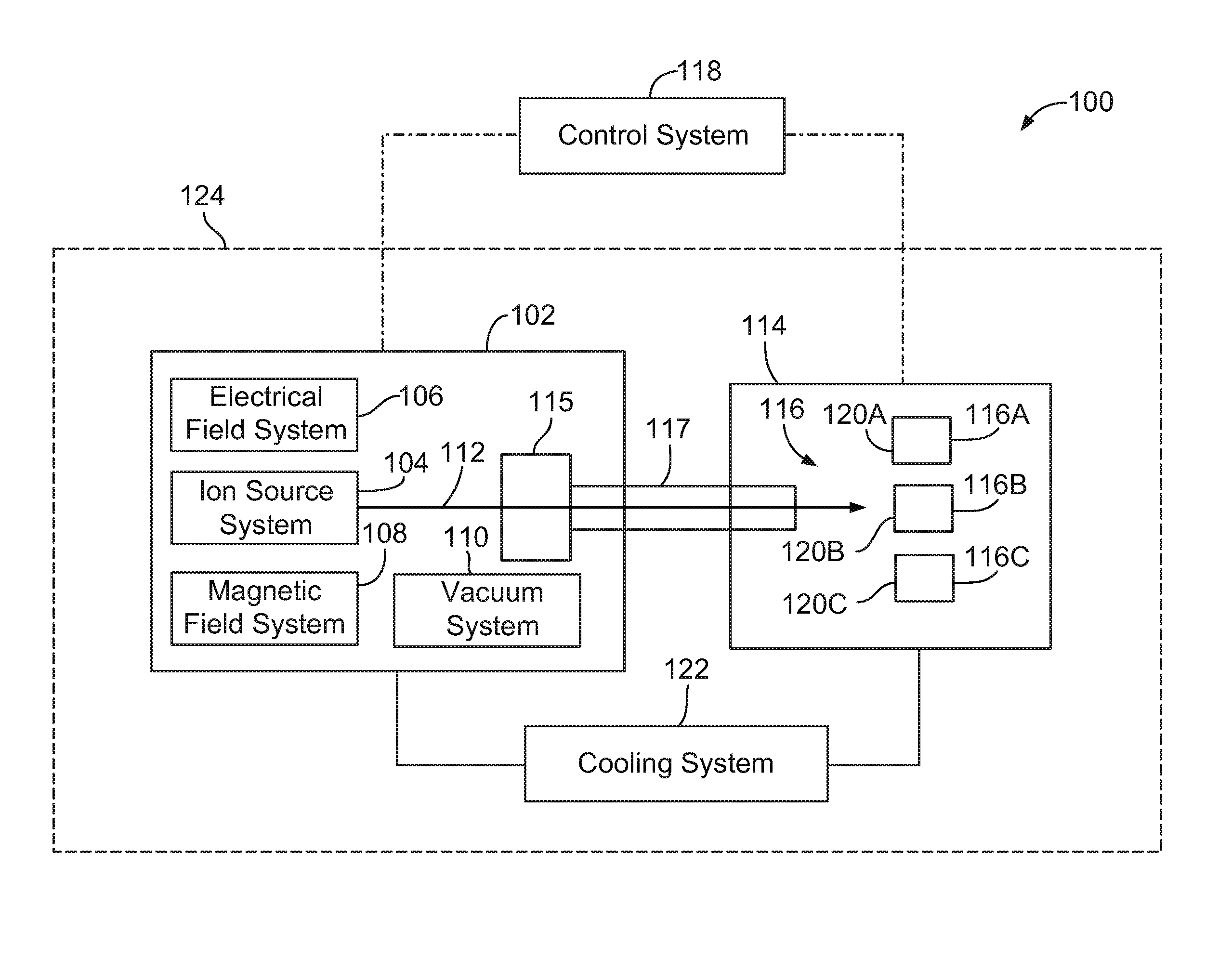
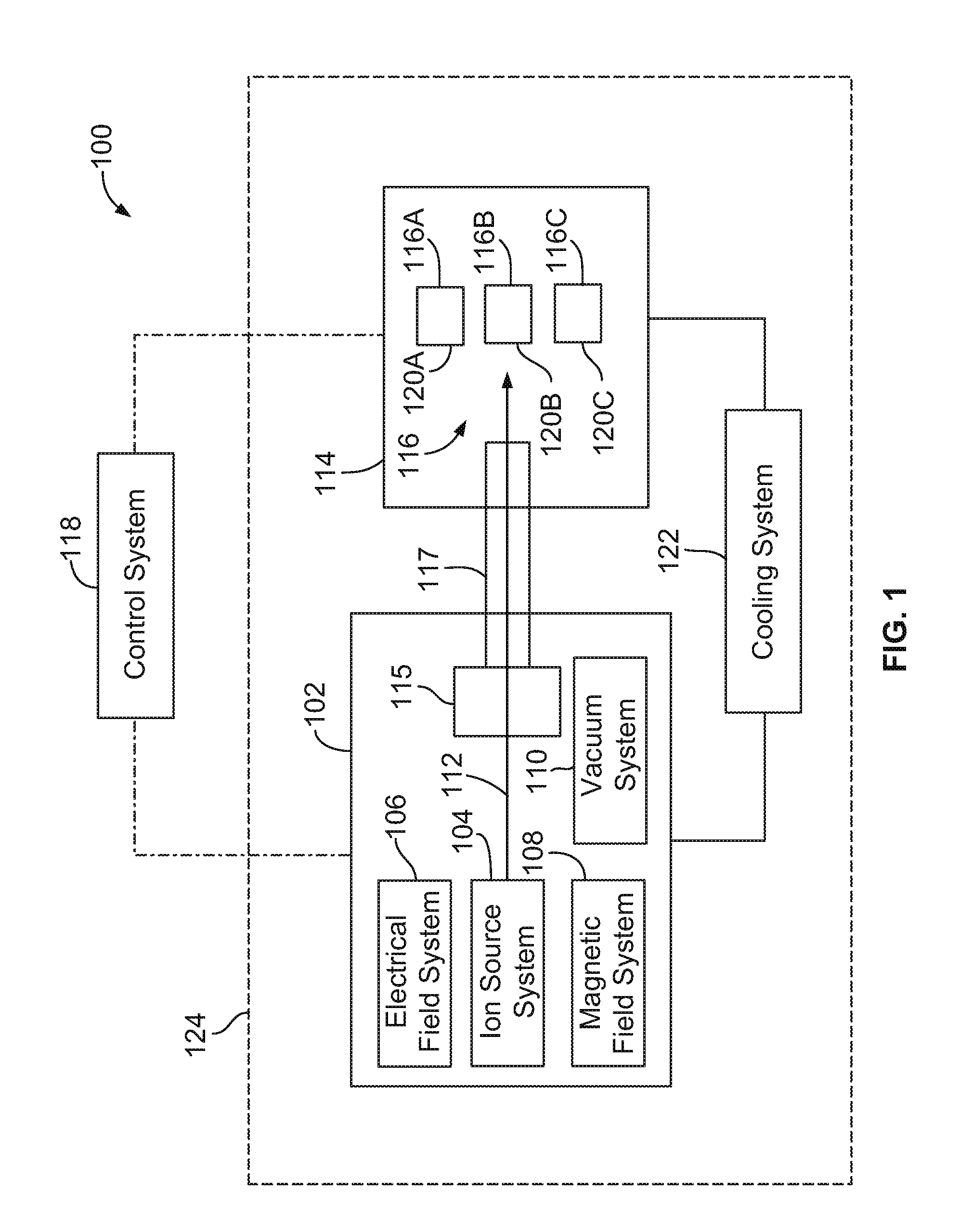
[0024]FIG. 1 is a block diagram of an isotope production system 100 formed in accordance with one embodiment. The system 100 includes a cyclotron 102 that has several sub-systems including an ion source system 104, an electrical field system 106, a magnetic field system 108, and a vacuum system 110. During use of the cyclotron 102, charged particles are placed within or injected into the cyclotron 102 through the ion source system 104. The magnetic field system 108 and electrical field system 106 generate respective fields that cooperate with one another in producing a particle beam 112 of the charged particles.

[0025]Also shown in FIG. 1, the system 100 has an extraction system 115 and a target system 114 that includes a target material 116. The target system 114 may be positioned adjacent to the cyclotron 102. To generate isotopes, the particle beam 112 is directed by the cyclotron 102 through the extraction system 115 along a beam transport path or beam passage 117 and into the ta...


PUM


Abstract

An isotope production system that includes a cyclotron having a magnet yoke that surrounds an acceleration chamber. The cyclotron is configured to direct a particle beam from the acceleration chamber through the magnet yoke. The isotope production system also includes a target system that is located proximate to the magnet yoke. The target system is configured to hold a target material and includes a radiation shield that extends between the magnet yoke and the target location. The radiation shield is sized and shaped to attenuate gamma rays emitted from the target material toward the magnet yoke. The isotope production system also includes a beam passage that extends from the acceleration chamber to the target location. The beam passage is at least partially formed by the magnet yoke and the radiation shield of the target system.

Description

CROSS-REFERENCES TO RELATED APPLICATIONS[0001]The present application includes subject matter related to subject matter disclosed in U.S. patent application Ser. No. 12 / 435,903 entitled “ISOTOPE PRODUCTION SYSTEM AND CYCLOTRON”; application Ser. No. 12 / 435,949 entitled “ISOTOPE PRODUCTION SYSTEM AND CYCLOTRON HAVING A MAGNET YOKE WITH A PUMP ACCEPTANCE CAVITY”; application Ser. No. 12 / 435,931 entitled “ISOTOPE PRODUCTION SYSTEM AND CYCLOTRON HAVING REDUCED MAGNETIC STRAY FIELDS”; all of which were filed on May 5, 2009 and all of which are incorporated by reference in their entirety.BACKGROUND OF THE INVENTION[0002]Embodiments of the invention described herein relate generally to isotope production systems, and more particularly to isotope production systems that may be safely used in relatively confined spaces, such as hospital rooms.[0003]Radioisotopes (also called radionuclides) have several applications in medical therapy, imaging, and research, as well as other applications that...

Claims


Application Information

Patent Timeline
Patent Type & Authority Applications(United States)
IPC IPC(8): G21B1/00G21C9/00G21C19/00
CPCG21G1/10H05H13/00H05H6/00Y02E30/10G21K5/00
Inventor NORLING, JONASERICKSSON, TOMAS
Owner GENERAL ELECTRIC CO
Why Eureka
Try Eureka