Optical connector

a technology of optical axis alignment and optical axis alignment, which is applied in the field of optical connectors, can solve the problems of high precision time-consuming operation in device fabrication, and the above-stated arts in patent literature still have problems, so as to achieve high accuracy in optical axis alignment and efficient pick up

Inactive Publication Date: 2010-12-30
ADVANCED CABLE SYST CORP +1
View PDF2 Cites 31 Cited by
  • Summary
  • Abstract
  • Description
  • Claims
  • Application Information

AI Technical Summary

Benefits of technology

[0015]In view of these circumstances, the object of the present invention is to provide an optical connector that requires no complicated fabrication operation such as highly accurate optical axis alignment and that permits an efficient pick up of part of the communication signal light being on-propagation along an optical transmission line.MEANS FOR SOLVING THE PROBLEMS
[0032]The present invention is able to provide an optical connector that requires no complicated fabrication operation such as highly accurate optical axis alignment and that permits an efficient pick up of part of the communication signal light being on-propagation along an optical transmission line.

Problems solved by technology

Above-stated arts in Patent Literatures however still have problems.
This feature requires a time consuming operation in fabrication of devices and demands a high precision in optical axis alignment.
Further, the photo-detector being comprised of a phosphor causes visual examination to be hard because luminescence time length of such detector is extremely short; therefore, there has faced a difficulty in practicability of the art to an optical communication-related facility.
In this configuration, stress applied on the waveguide of resin interposed within the gap attributable to insertion and extraction of the ferrule (optical fiber) may cause flaking-off or abrasion on the waveguide.
This situation is a problem in that the efficient guiding of the communication signal light to outside is not available and consequently in that the detecting of communication signal light with accuracy maintained over the long term is not feasible.
Further, there is another problem in that the gap spacing control is difficult because the gap distance is adjusted relying on the loss measurement of the communication signal light using a power monitor.
In addition, this feature requires a time consuming operation in fabrication of devices and demands a high precision in optical axis alignment.
Further, parts of the device such as the optical waveguide substrate are expensive.
This situation has made it difficult to realize cost cutting for more spread practical use.
The art defined in JP 2003-218813A also has had a problem in that visual examination is hard because the luminescence time length of a visible light transducer is extremely short.

Method used


Image

  • Optical connector
  • Optical connector
  • Optical connector

Examples


first embodiment

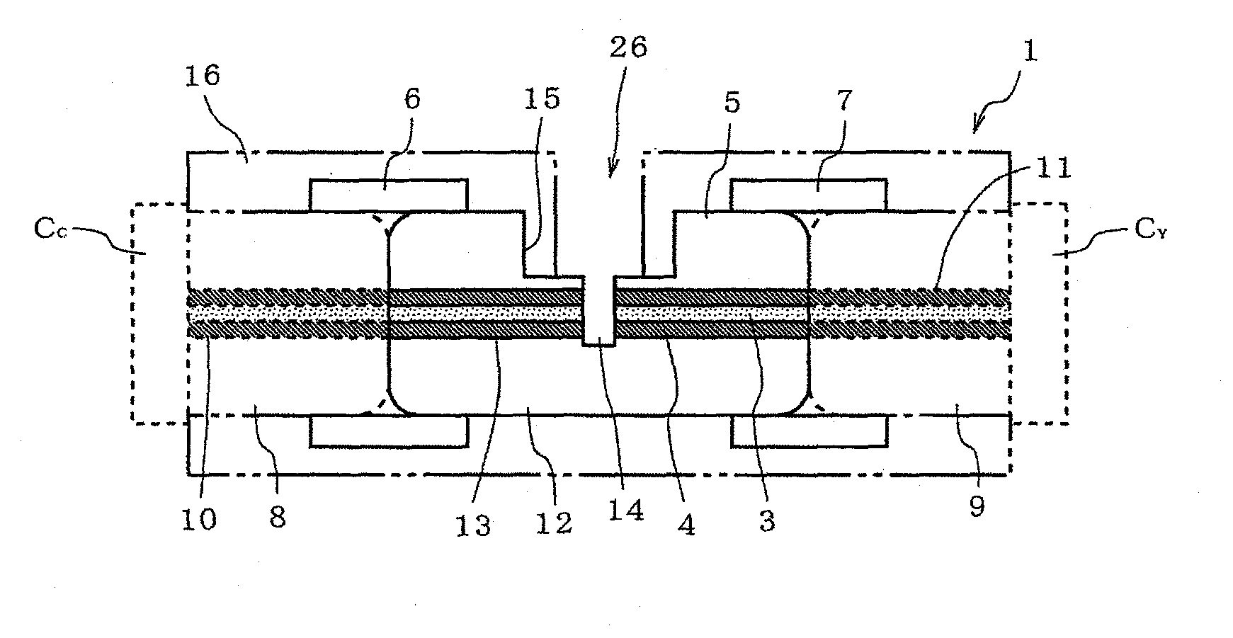
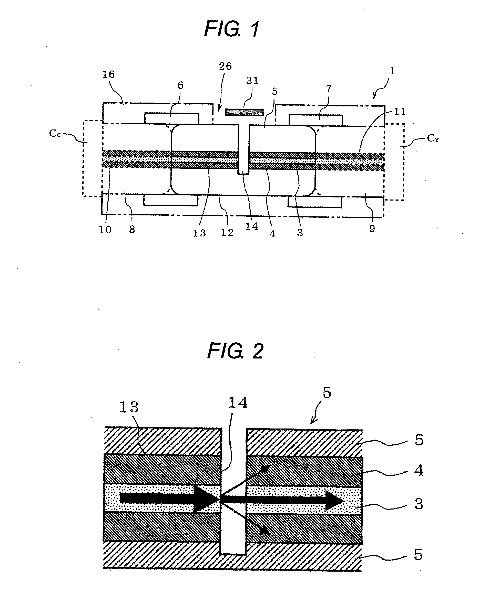
[0048]FIG. 1 is a schematic sectional view of an optical connector in the present invention.

[0049]As FIG. 1 illustrates, an optical connector 1 is a device that optically connects optical transmission lines each other, picks up part of the communication signal light, and outputs the picked up communication signal light to a light-reception component 31 of a light detector 2 (FIG. 1 illustrates part of the light detector 2). The light detector 2, details of which will be described later, is a device for detecting the picked up communication signal light. As the light detector 2 has a structure separate from the optical connector 1, the light detector 2 is attached on the optical connector 1 in a detachable manner. With this configuration, the optical connector 1 can be small-sized and further one light detector 2 is applicable commonly to a plurality of the optical connectors 1 greatly attributing to cost cutting.

[0050]The optical connector 1 has a joining element 5 inside a connecto...

second embodiment

[0093]An optical connector by the second embodiment is characterized in that part of the core 3 of the joining element 5 is partly given a longitudinal shape modification. More particularly, micro-bend (undulation) partly formed on the joining element 5 functions as the light pick-up means.

[0094]As illustrated in FIGS. 8A to 8C, a micro-bend 41 is an undulating portion formed on such a portion of the core 3 of the joining element 5 as faces the light reception component of the light detector.

[0095]Forming the micro-bend 41 on purpose on the core products a transmission loss of the communication signal light, in other words, generates leakage light. Detecting this leakage light with the light reception component 31 of the light detector 2 enables examination of existence of communication signal light.

[0096]The micro-bend 41 is formed by providing a hole having periodical bend in the ferrule 12 in which the optical fiber 13 is to be embedded and then inserting the optical fiber 13 int...

third embodiment

[0101]An optical connector by the third embodiment is characterized in that the light is picked up at the end face of the joining element 5 that is an optical connection interface with the optical transmission line. More specifically, such optical connection is constituted in a manner, wherein the insertion hole of the ferrule 12, into which the optical fiber 13 is to be inserted, is positioned at a location shifted from the inline position of the holes of the ferrules 8 and 9 to be connected, as illustrated in FIG. 10A, and thereby the optical connection is established at the connecting point (connecting end faces) of the ferrule 12 with the optical axis of the core (the core 3) of the optical fiber 13 shifted from the optical axes of the optical fibers 10 and 11 of the transmission line. In FIG. 10A, the shift of the hole of the ferrule 12 is illustrated upwards in the figure; however, shifting downwards in the figure is also feasible.

[0102]Instead, it is practicable to cause the ...


PUM


Abstract

An optical connector that requires no complicated fabrication operation such as highly accurate optical axis alignment and that permits an efficient pick up of part of the communication signal light being on-propagation along an optical transmission line, is provided. The optical connector 1 for connecting optical transmission lines each other is comprised of at least a connector main body 16 and a joining element 5 provided inside the connector main body 16 being interposed between the optical transmission lines and coupled to each end face of the optical transmission lines, wherein the joining element 5 is comprised of a core 3 and a cladding 4 provided on the periphery of the core 3 that are optically coupled to the optical transmission line, and a light pick-up means for picking up part of communication signal light being on-propagation along the optical transmission line, and wherein the connector main body 16 has, in a position that faces the light pick-up means, an optical output port 26 for outputting part of the communication signal light picked up by the light pick-up means to a light detector 2.

Description

TECHNICAL FIELD[0001]The present invention relates to an optical connector that has a joining element inside the main body thereof to establish an optical connection between optical transmission lines enabling examination of communication status of the optical transmission line, wherein the joining element is comprised of a core and a cladding that are optically coupled to the optical transmission line.BACKGROUND ART[0002]The communication signal light propagating along an optical transmission line is mostly invisible light that does not exist in the range of visible lights. Therefore, the visual examination is not applicable to operations in an optical communication facility such as a data center or an equipment office. Consequently, there have been problems such that it is not easy to determine whether a specific optical transmission line is in use or not and such that misunderstanding of a working optical transmission line being not-working causes accidental extraction of a worki...

Claims


Application Information

Patent Timeline
Patent Type & Authority Applications(United States)
IPC IPC(8): G02B6/26
CPCG02B6/2852G02B6/4214G02B6/3825
Inventor KOJIMA, SEIJISUZUKI, KANAKONAKATANI, YOSHIHIROISHIKAWA, TOSHIHIKONISHIKAWA, TAKAOITO, KOJIROSUEOKA, TETSUYA
Owner ADVANCED CABLE SYST CORP
Why Eureka
Try Eureka