Dimpled Light Collection and Concentration System, Components Thereof, and Methods

a light collection and concentration system technology, applied in the field of optical light guides, can solve problems such as non-ideal light guides, and achieve the effect of improving light concentration

Active Publication Date: 2010-12-30
UNIVERSITY OF ROCHESTER +1
View PDF16 Cites 27 Cited by
  • Summary
  • Abstract
  • Description
  • Claims
  • Application Information

AI Technical Summary

Benefits of technology

[0016]The combination of a light injection element and a bypass element of any type or form described herein will be referred to herein as a “dimple”. A light guide including a guide layer with one or more dimples will be referred to herein as a “dimpled light guide”. Dimpled light guides are a form of non-imaging light concentrator that allow for improved light concentration in a thin and lightweight form factor.

Problems solved by technology

By concentrating solar energy with optics, less photovoltaic (PV) material is used, reducing cost, since PVs are expensive and energy-intensive to produce compared with optical components.
The presence of the light injection elements results in a non-ideal light guide since light propagation through the transport structure is hindered by interactions with downstream light injection elements.

Method used


Image

  • Dimpled Light Collection and Concentration System, Components Thereof, and Methods
  • Dimpled Light Collection and Concentration System, Components Thereof, and Methods
  • Dimpled Light Collection and Concentration System, Components Thereof, and Methods

Examples


Embodiment Construction

[0038]Reference will now be made in detail to the present exemplary embodiments of the invention, examples of which are illustrated in the accompanying drawings. Wherever possible, the same reference numbers will be used throughout the drawings to refer to the same or like parts.

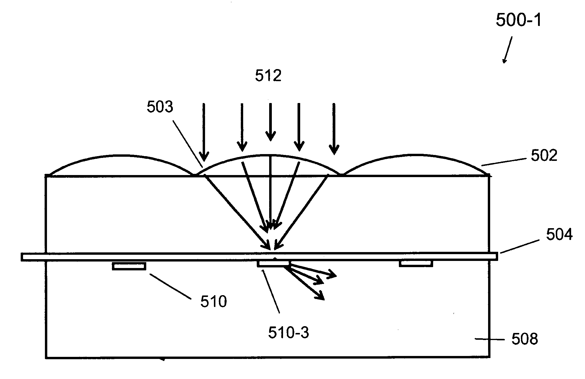
[0039]A ‘dimple’ according to a representative aspect of the invention is shown in FIG. 3, and is designated generally throughout by reference numeral 10. As used herein in accordance with a non-limiting embodiment of the invention, the term ‘dimple’ refers to a structural component of a planar light guide. As illustrated in FIG. 3, the dimple 10 is composed of two parts: a light injection element 11 and a light bypass element 12. Each injection element in the light guide is located to receive focused or near-focus light from a respective primary light concentrator element (e.g., lenslet) as described in greater detail below. In the instant aspect, the injection element acts to redirect light from a directio...


PUM


Abstract

A light guide apparatus includes a light guide layer further including light injection elements and respective light bypass elements disposed optically upstream of the light injection elements. The light injection elements and / or the bypass elements can take the form of injection facets (air prisms), surface diffraction elements, volume diffraction elements, and gradient index profiles. A light collection and concentration system comprises a single light guide apparatus, a light-transmitting medium layer disposed immediately adjacent the single light guide apparatus, and a primary light concentrator component disposed adjacent the light-transmitting medium layer, including a plurality of primary concentrator elements each of which is in optical registration with a respective one of the light injection elements of the single light guide apparatus.

Description

JOINT RESEARCH AGREEMENT[0001]This application is derived from a pre-existing Joint Research Agreement between the assignee of the instant application, the University of Rochester, and Abengoa Solar New Technologies, S.A.CROSS-REFERENCE TO RELATED APPLICATIONS[0002]This application is a Divisional application of U.S. Ser. No. ______ (Atty. Docket No. 610P041) entitled Stepped Light Collection and Concentration System, Components Thereof, and Methods, filed concurrently with the instant application, the disclosure of which is incorporated by reference herein in its entirety.BACKGROUND OF THE INVENTION[0003]1. Field of the Invention[0004]Embodiments of the invention relate generally to the field of optical light guides and, more particularly, to non-imaging, light concentrator systems, methods, and applications. Even more particularly, embodiments of the invention relate to a light collection and concentration system used for a concentrated photo-voltaic (CPV) solar energy system, and...

Claims


Application Information

Patent Timeline
Patent Type & Authority Applications(United States)
IPC IPC(8): G02B6/10
CPCF24J2/067F24J2/08H01L31/0547Y02E10/52H01L31/0543G02B6/0036F24S23/12F24S23/30
Inventor MOORE, DUNCAN T.SCHMIDT, GREG R.UNGER, BLAIR L.
Owner UNIVERSITY OF ROCHESTER
Why Eureka
Try Eureka