Control of overheating in an image fixing assembly

a technology of fixing assembly and control panel, which is applied in the direction of electrographic process apparatus, instruments, optics, etc., can solve the problems of thermal gradient increase, damage to the image fixing assembly and components, roll fuser damage, etc., and achieve the effect of reducing thermal gradient, reducing thermal gradient, and enhancing throughput of image forming apparatus

Active Publication Date: 2010-12-30
LEXMARK INT INC
View PDF3 Cites 8 Cited by
  • Summary
  • Abstract
  • Description
  • Claims
  • Application Information

AI Technical Summary

Benefits of technology

[0018]In view of the foregoing disadvantages inherent in the prior art, the general purpose of the present disclosure is to control overheating in an image fixing assembly, to include all the advantages of the prior art, and to overcome the drawbacks inherent therein.
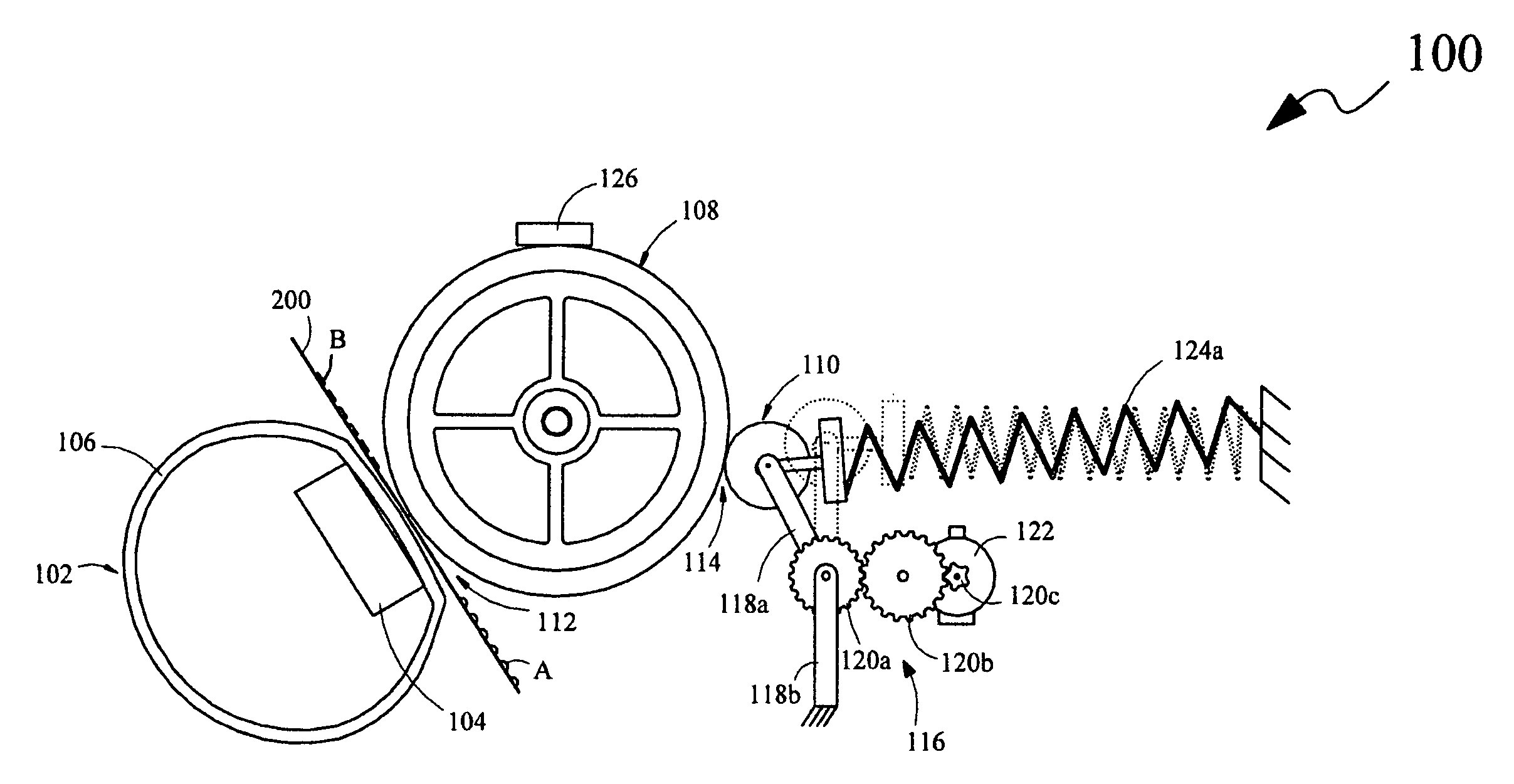
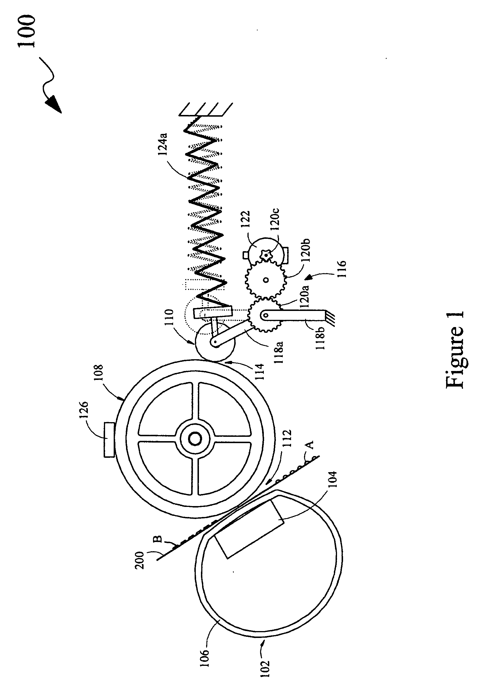
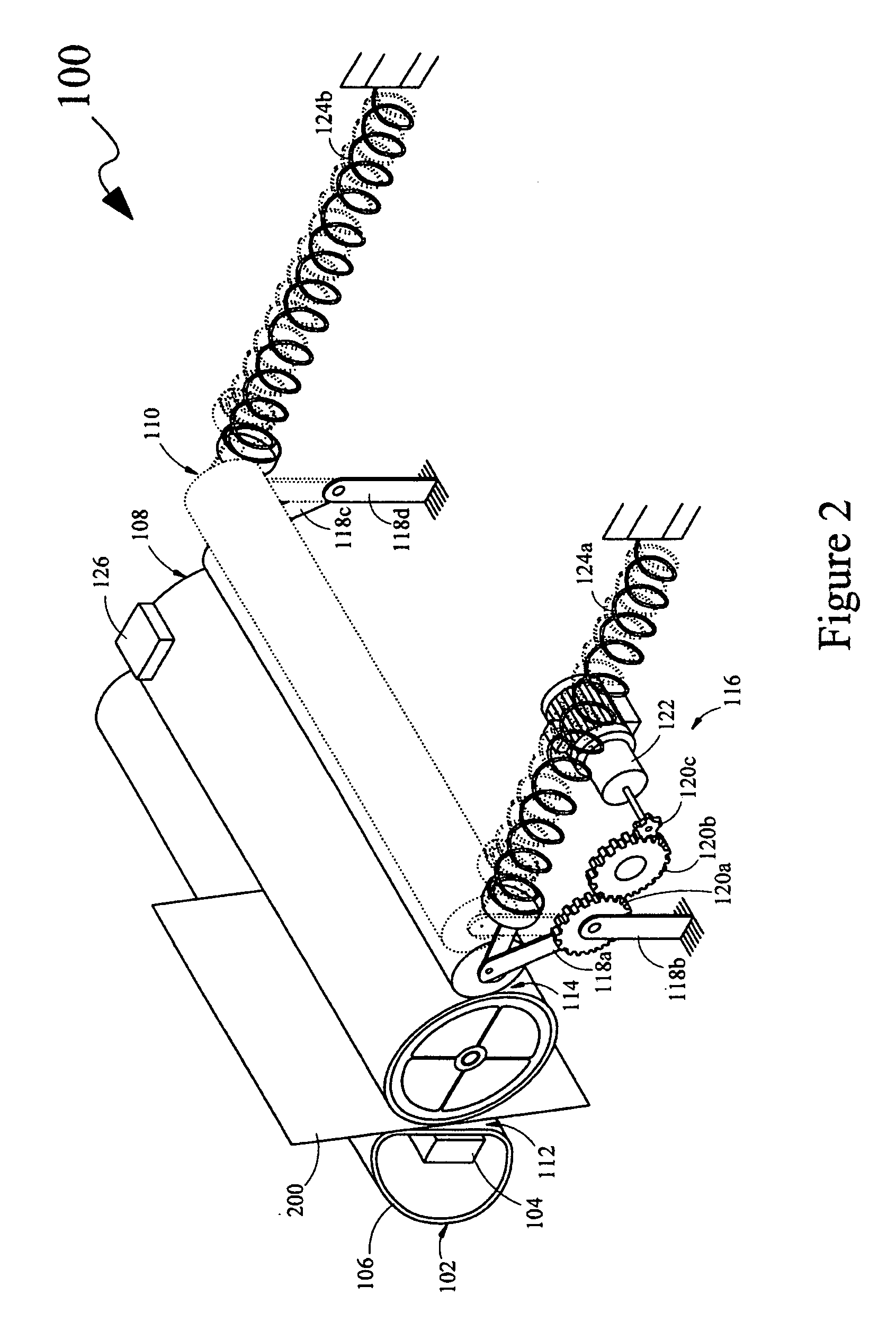
[0019]In one aspect, the present disclosure provides an image fixing assembly for an image forming apparatus. The image fixing assembly comprises a heating unit, a backup member, and a heat conducting member. The heating unit comprises a heating element, and a fusing member that encloses the heating element. Further, the fusing member is configured to rotate around the heating element, and is capable of being heated by the heating element. The backup member is abuttingly coupled to the fusing member for configuring a nip portion therebetween. Furthermore, the backup member is capable of pressing media sheets against the fusing member when the media sheets pass through the nip portion. The heat conducting member is capable of retractably coupling to one of the fusing member and the backup member for configuring a thermal conduction path therebetween for enabling flow of heat between the one of the fusing member and the backup member, and the heat conducting member, for reducing a thermal gradient on at least one of the fusing member and the backup member. The reduction of the thermal gradient on the at least one of the fusing member and the backup member allows for the reduction of an inter-page gap between the media sheets passing through the nip portion, thereby enhancing throughput of the image forming apparatus.

Problems solved by technology

Further, there is a gradual increase in the thermal gradient in such an image fixing assembly after printing several consecutive narrow media sheets.
Accordingly, high temperatures at the portions of the fusing member and the backup member where a narrow media sheet is not present may cause damage to the image fixing assembly and components thereof.
In addition, a hot roll fuser system employed as the image fixing assembly in an image forming apparatus is associated with a high thermal mass.
However, fixing of a first image during printing of media sheets using the hot roll fuser system, which employs the fuser roll having the large thermal mass, becomes time-consuming, as there may exist a delay in raising the temperature of the fuser roll prior to printing.
Specifically, the large thermal mass of the hot roll fuser system leads to a long warm-up time for printing a first media sheet.
Further, printing narrow media sheets may gradually lead to failure of the hot roll fuser system.
Further, the lower amount of metal in the belt fuser system results in a lower axial thermal conductivity as opposed to the hot roll fuser system.
Furthermore, the lower thermal mass leads to a short warm-up time for printing a first media sheet as opposed to the printing of the first media sheet using the hot roll fuser system.
However, the lower axial thermal conductivity of the fusing member of the belt fuser system poses difficulty while printing narrow media sheets.
Specifically, a high thermal gradient is generated after successive printing of narrow media sheets due to the lower axial thermal conductivity, which may lead to a failure of the belt fuser system.
Consequently, generation of a high thermal gradient may severely impact throughput of the belt fuser system.
Moreover, a delay before printing full width media sheets may be required after printing several narrow media sheets using either the hot roll fuser system or the belt fuser system.
Additionally, generation of the thermal gradient, particularly, generation of a high temperature on portions of the fusing member and the backup member may cause a defect in print quality, as unfused toner tends to stick to the heating unit instead of properly adhering to a media sheet.
This problem may be prominent in the belt fuser system, since the belt fuser system requires a longer time period for recovering from a state with a high thermal gradient, due to less conduction of heat between the portions not covered by media sheets and the portions covered by the media sheets.
Accordingly, printing of full width media sheets after printing of narrow media sheets using such a technique proves to be time-consuming due to the delay required for turning off of the heating element for reducing the thermal gradient and then turning the heating element on for maintaining a requisite temperature prior to subsequent rounds of printing full width media sheets after printing narrow media sheets.
Further, in the absence of the temperature sensing member, a pre-determined time delay may be introduced before continuing printing of narrow media sheets.
Accordingly, an increase in the inter-page gap and / or introduction of the pre-determined time delay results in reduction of throughput for printing narrow media sheets and full width media sheets by the image fixing assembly.

Method used


Image

  • Control of overheating in an image fixing assembly
  • Control of overheating in an image fixing assembly
  • Control of overheating in an image fixing assembly

Examples


Embodiment Construction

[0027]It is to be understood that various omissions and substitutions of equivalents are contemplated as circumstances may suggest or render expedient, but these are intended to cover the application or implementation without departing from the spirit or scope of the claims of the present disclosure. It is to be understood that the present disclosure is not limited in its application to the details of components set forth in the following description. The present disclosure is capable of other embodiments and of being practiced or of being carried out in various ways. Also, it is to be understood that the phraseology and terminology used herein is for the purpose of description and should not be regarded as limiting. The use of “including,”“comprising,” or “having” and variations thereof herein is meant to encompass the items listed thereafter and equivalents thereof as well as additional items. Further, the terms “a” and “an” herein do not denote a limitation of quantity, but rathe...


PUM


Abstract

An image fixing assembly includes a heating unit having a heating element and a fusing member enclosing the heating element; a backup member; and a heat conducting member. The fusing member is configured to rotate around the heating element. Further, the fusing member is capable of being heated by the heating element. The backup member is abuttingly coupled to the fusing member for configuring a nip portion therebetween, and is capable of pressing media sheets against the fusing member, when the media sheets pass through the nip portion. The heat conducting member is capable of retractably coupling to one of the fusing member and the backup member for enabling flow of heat between the one of the fusing member and the backup member, and the heat conducting member, for reducing a thermal gradient. Further disclosed is a method for fixing images on the media sheets using the image fixing assembly.

Description

CROSS REFERENCES TO RELATED APPLICATIONS[0001]None.STATEMENT REGARDING FEDERALLY SPONSORED RESEARCH OR DEVELOPMENT[0002]None.REFERENCE TO SEQUENTIAL LISTING, ETC.[0003]None.BACKGROUND[0004]1. Field of the Disclosure[0005]The present disclosure relates generally to an image fixing assembly of an image forming apparatus, and more specifically, to controlling overheating in an image fixing assembly of an image forming apparatus in order to enhance throughput of the image forming apparatus while printing media sheets.[0006]2. Description of the Related Art[0007]In an image forming apparatus, such as an electrophotographic printing apparatus, unfused toner images (i.e., latent images) are fixed on a media sheet by an image fixing assembly of the image forming apparatus. Typically, an image fixing assembly of an image forming apparatus includes a heating unit having a heating element and a fusing member, and a backup member abuttingly coupled to the fusing member of the heating unit. Furt...

Claims


Application Information

Patent Timeline
Patent Type & Authority Applications(United States)
IPC IPC(8): G03G15/20
CPCG03G15/2039G03G15/2032
Inventor CAO, JICHANGCOOK, WILLIAM PAULKIETZMAN, JOHN WILLIAM
Owner LEXMARK INT INC
Why Eureka
Try Eureka