Efficient Vision and Kinematic Data Fusion For Robotic Surgical Instruments and Other Applications

a robotic surgical instrument and kinematic data technology, applied in the field of robotic surgical instruments and other applications, can solve the problems of computational difficulties in fusing joint-based and image-based data, and the absolute location and orientation of the end effector determined from this joint-based data may not match the image of the end effector shown to the surgeon at the control console, so as to enhance the overall accuracy, simple rigid transformation, and simple and relatively stable adjustment or bias offset

Active Publication Date: 2010-12-30
INTUITIVE SURGICAL OPERATIONS INC
View PDF101 Cites 185 Cited by
  • Summary
  • Abstract
  • Description
  • Claims
  • Application Information

AI Technical Summary

Benefits of technology

[0010]The present invention generally provides improved robotic devices, systems, and methods, particularly for use in telesurgical therapies through minimally invasive apertures such as endoscopic cannula sleeves, a natural orifice, or the like. Embodiments of the invention may make use of joint-based data throughout much of the robotic kinematic chain, but may selectively rely on information from an image capture device (such as an endoscope or the like). This image-based data may be used to correct or define a pivotal center at which a shaft of the robotic surgical tool enters the patient. More specifically, robotic surgical tools (like known endoscopic tools) may have elongate shafts which pivot at a pivot point adjacent the aperture into the patient. Rather than attempting to recalculate or adjust joint data along the entire kinematic chain of the tool, based on an image, applying a simple and relatively stable adjustment or bias offset to an orientation along the shaft and the location at the pivotal center may significantly enhance the overall accuracy with which tool movements can be tracked. The shaft orientation and pivotal center location can define a remote center pose which is useful for these calculations. Advantageously, the bias offset may be applied as a simple rigid transformation from the image-based pivotal center pose to a joint-based pivotal center pose. This simple change may effectively replace the joint-based remote center pose with an image-based remote center pose within a processor module that tracks an end effector, calculates robotic movement commands of a tool or manipulator supporting the tool, calculates end effector movement distances, super imposes graphical overlays on the tool images, or the like. Advantageously, the system can gain much more accurate information recording the end effector without having to rigorously calculate a general solution of the tool kinematic chain based on the combination of the joint data and image data, thereby saving computational time and resources while accurately adjusting for much of the environmental constraints mechanically imposed on the system. Alternative embodiments may identify stationary or variable errors of other joints or linkages in the kinematic chain. A variety of enhancements to robotic surgery (including displaying of graphical overlays collocated with images of the physical tools, enhanced three dimensional measurements obtained robotically using the tools, collision detection, and the like) may benefit from the enhancements in pose information precision available with the methods and systems described herein.

Problems solved by technology

While such joint-based information provides quite accurate relative movements of the end effector, the correlation between the absolute location and orientation of the end effector determined from this joint-based data may not precisely match the image of the end effector shown to the surgeon at the control console.
Although there have been proposals to enhance the accuracy of joint data using image-based information acquired from the endoscope of the telesurgical system, fusing the joint-based and image-based data can be computationally challenging.

Method used


Image

  • Efficient Vision and Kinematic Data Fusion For Robotic Surgical Instruments and Other Applications
  • Efficient Vision and Kinematic Data Fusion For Robotic Surgical Instruments and Other Applications
  • Efficient Vision and Kinematic Data Fusion For Robotic Surgical Instruments and Other Applications

Examples


Embodiment Construction

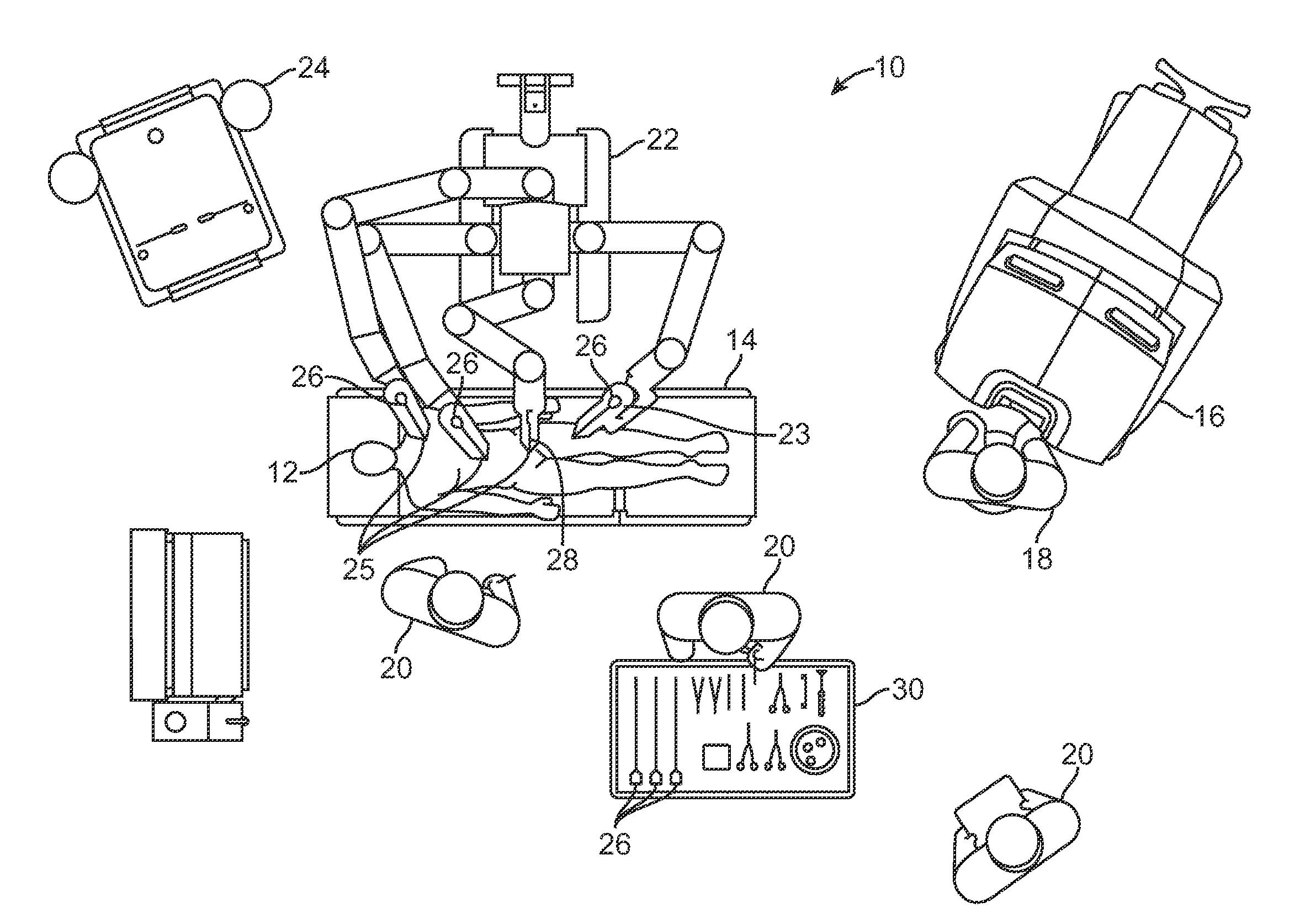
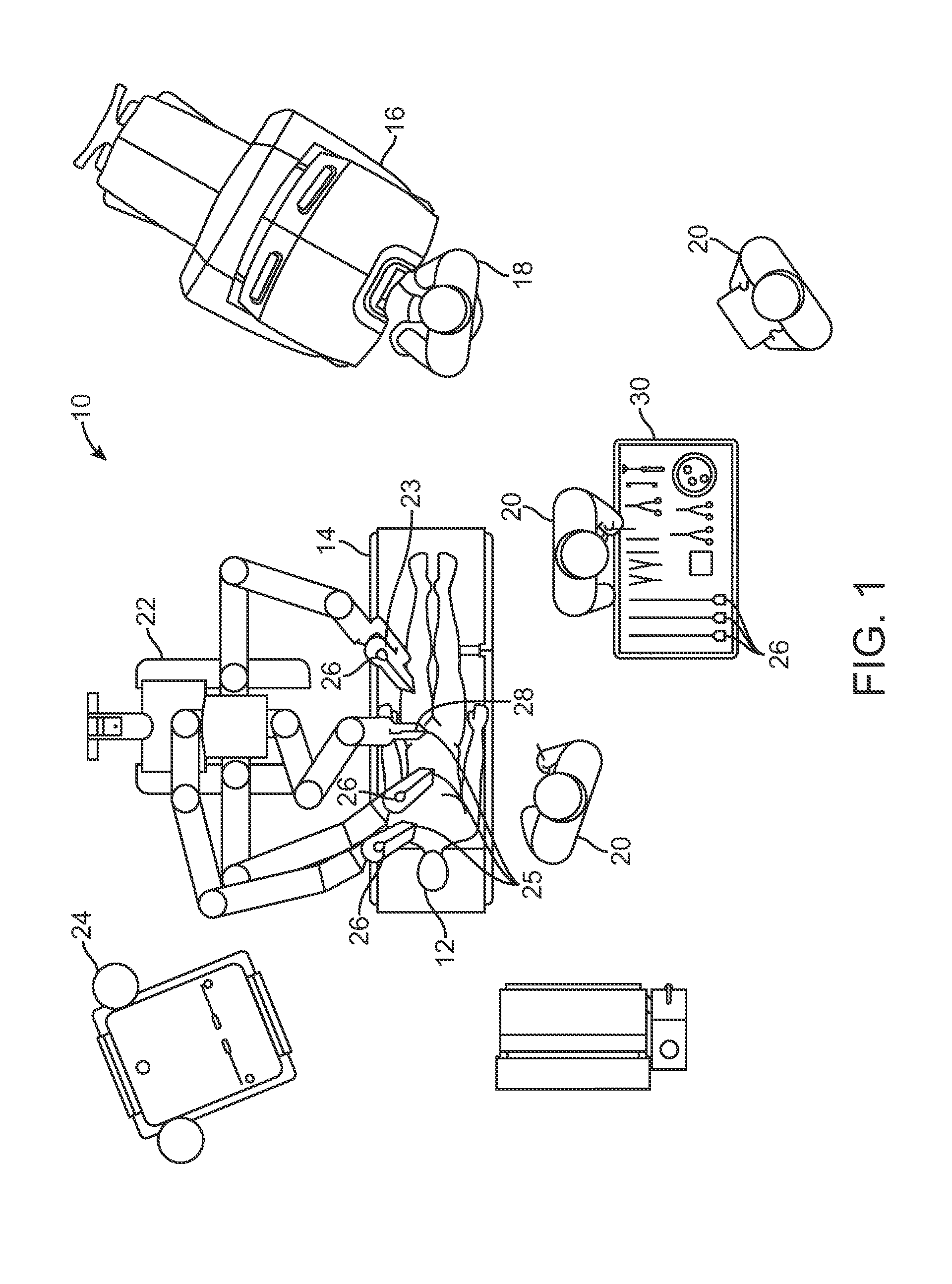
[0044]The present invention generally provides improved robotic surgical devices, systems, and methods, particularly for telesurgery and other medical robotic applications. Embodiments of the present invention will find their most immediate use for correcting pose information (including position and / or orientation) of robotic surgical tools inserted through minimally invasive apertures to an internal surgical site. While existing robotic telesurgical systems do a good job of establishing and maintaining correspondence between movement of the master input device and movement of the end effector at an internal surgical site (as displayed to the surgeon), still further advantages may be obtained by providing more accurate information regarding the position and / or orientation of the tool (including the end effector, an elongate shaft of the tool extending through a minimally invasive aperture, linkages coupling the shaft to the end effector, and the like).

[0045]While robotic surgical ap...


PUM


Abstract

Robotic devices, systems, and methods for use in telesurgical therapies through minimally invasive apertures make use of joint-based data throughout much of the robotic kinematic chain, but selectively rely on information from an image capture device to determine location and orientation along the linkage adjacent a pivotal center at which a shaft of the robotic surgical tool enters the patient. A bias offset may be applied to a pose (including both an orientation and a location) at the pivotal center to enhance accuracy. The bias offset may be applied as a simple rigid transformation from the image-based pivotal center pose to a joint-based pivotal center pose.

Description

CROSS-REFERENCES TO RELATED APPLICATIONS[0001]The present application is related to U.S. patent application Ser. No. 12 / 428,657 filed on Apr. 23, 2009, entitled “Fiducial Marker Design And Detection For Locating Surgical Instruments In Images” (Attorney Docket No. ISRG 01480 / US); U.S. patent application Ser. No. 12 / 428,691 filed on Apr. 23, 2009, entitled “Configuration Marker Design And Detection For Instrument Tracking” (Attorney Docket No. ISRG 01910 / US); U.S. patent application Ser. No. 12 / 415,354 filed on Mar. 31, 2009, entitled “Synthetic Representation Of A Surgical Robot” (Attorney Docket No. ISRG 01940 / US); U.S. patent application Ser. No. 12 / 485,503 filed on Jun. 16, 2009, entitled “Virtual Measurement Tool For Minimally Invasive Surgery” (Attorney Docket No. ISRG 01930 / US); U.S. patent application Ser. No. 11 / 130,471 filed on May 16, 2005, entitled “Methods and System for Performing 3-D Tool Tracking By Fusion of Sensor and / or Camera Derived Data During Minimally Invasive...

Claims


Application Information

Patent Timeline
Patent Type & Authority Applications(United States)
IPC IPC(8): A61B19/00
CPCA61B19/2203A61B2019/5437A61B2019/5265A61B2019/5259A61B34/30A61B2034/2059A61B2034/2065A61B2090/3937
Inventor ZHAO, TAOZHAO, WENYIHOFFMAN, BRIAN DAVIDNOWLIN, WILLIAM C.HUI, HUA
Owner INTUITIVE SURGICAL OPERATIONS INC
Why Eureka
Try Eureka