Flexible wrist-type element and methods of manufacture and use thereof

a wrist-type element and flexible technology, applied in the field of flexible wrist-type elements, can solve the problems of high drag and bending force of flexible push-pull cables, inability to effectively combine axial and rotary movements so as to allow effective and precise use, and complex cable-pulley mechanisms. complex and feebl

Active Publication Date: 2010-12-30
CAREFUSION 2200 INC
View PDF2 Cites 85 Cited by
  • Summary
  • Abstract
  • Description
  • Claims
  • Application Information

AI Technical Summary

Benefits of technology

[0018]In another aspect, the flexible wrist-type element described above may further comprise a guide housing movably connected to the body housing and the hub, wherein the guide housing is further movably connected to at least one of the plurality of couplings and comprises a support surface supporting the at least one of the plurality of couplings during movement of the first end of the hub to the first position defining the first angle. Optionally, in this aspect, the support surface may limit an amount of pivoting between the plurality of couplings. In another option of this aspect, the support surface may prevent portions of the plurality of couplings from collapsing under compression and maintains alignment of the plurality of couplings under extension. In yet another option, the body housing may comprise an extension adjacent to the hub, wherein the extension comprises an inner wall defining a first slot, wherein the guide housing further comprises a support element, and further comprising a guide element having a first guide end, a second guide end and a second slot, wherein the first guide end is movably connected to the body housing within the first slot, wherein the second guide end is movably connected to the hub, and wherein the support element of the guide housing is movably connected within the second slot of the guide element such that the second slot defines a limit for movement of the plurality of couplings. Additionally, in another option, the first slot may define an angular limit of the first angle, and wherein the second slot defines an axial limit of movement of the plurality of couplings in response to the input force comprising the axial force. In a further option, the guide housing is connected to the at least one of the plurality of couplings at one of the plurality of joints. In yet another option, the flexible wrist-type element may further comprise a bearing element positioned between the support surface and the at least one of the plurality of couplings, wherein the bearing element allows the at least one of the plurality of couplings to rotate relative to the guide housing.

Problems solved by technology

Some mechanisms have been produced in the related art, including push-pull cables in guide tubes, pulley-cable mechanisms, and hydraulic mechanisms, however, none of these related art mechanisms effectively combine such motions as axial and rotary movements so as to allow effective and precise use.
For example, flexible push-pull cables have high drag and bending forces; cable-pulley mechanisms are complex and feeble; and hydraulic mechanisms typically are bulky and limited by hose travel.

Method used


Image

  • Flexible wrist-type element and methods of manufacture and use thereof
  • Flexible wrist-type element and methods of manufacture and use thereof
  • Flexible wrist-type element and methods of manufacture and use thereof

Examples


Embodiment Construction

[0051]Aspects of the present invention now will be described more fully hereinafter with reference to the accompanying drawings, in which variations and aspects of the present invention are shown. Aspects of the present invention may, however, be realized in many different forms and should not be construed as limited to the variations set forth herein; rather, these variations are provided so that this disclosure will be thorough and complete in the illustrative implementations, and will fully convey the scope thereof to those skilled in the art.

[0052]Unless otherwise defined, all technical and scientific terms used herein have the same meaning as commonly understood by one of ordinary skill in the art to which aspects of the present invention belong. The methods and examples provided herein are illustrative only and not intended to be limiting.

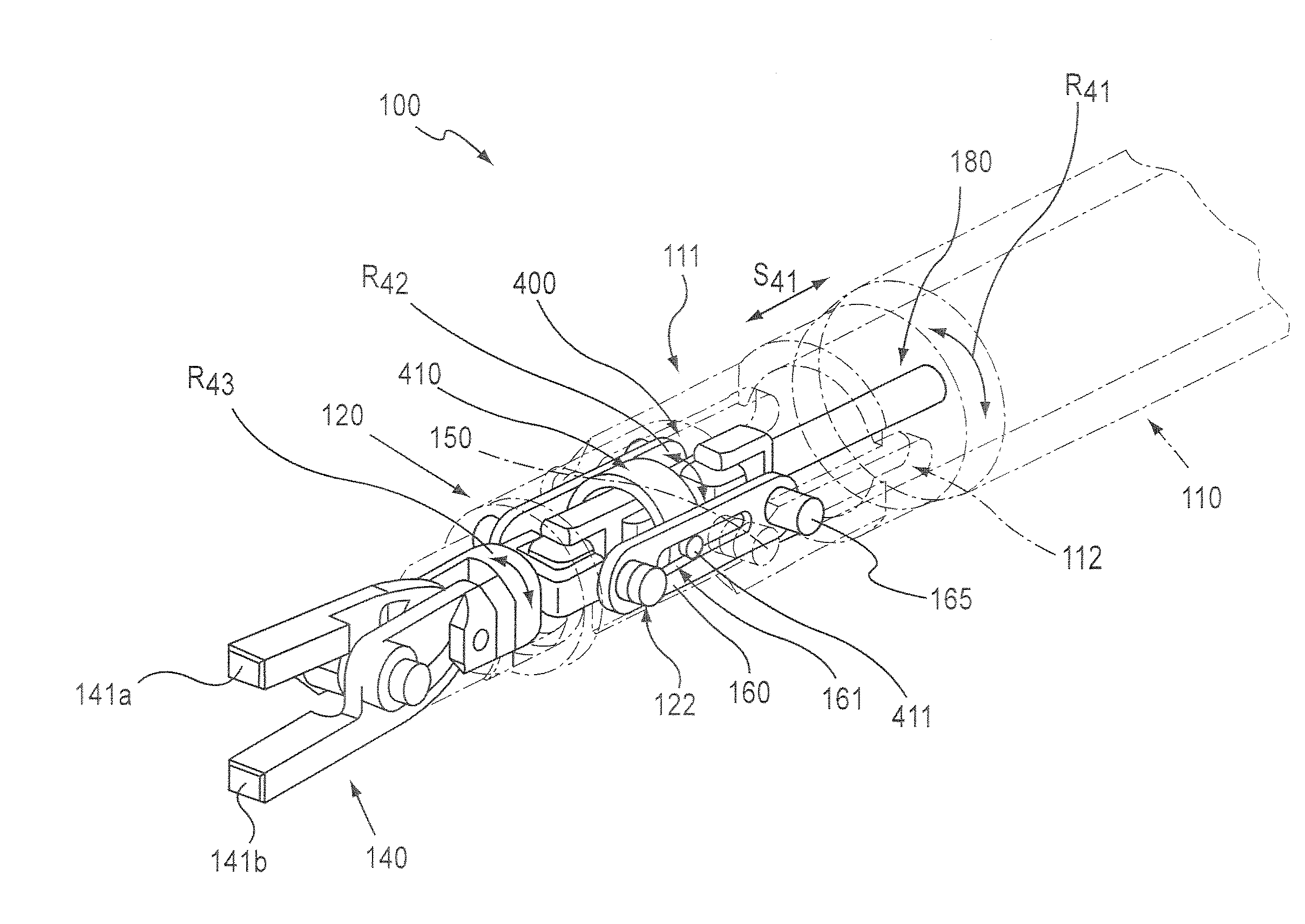
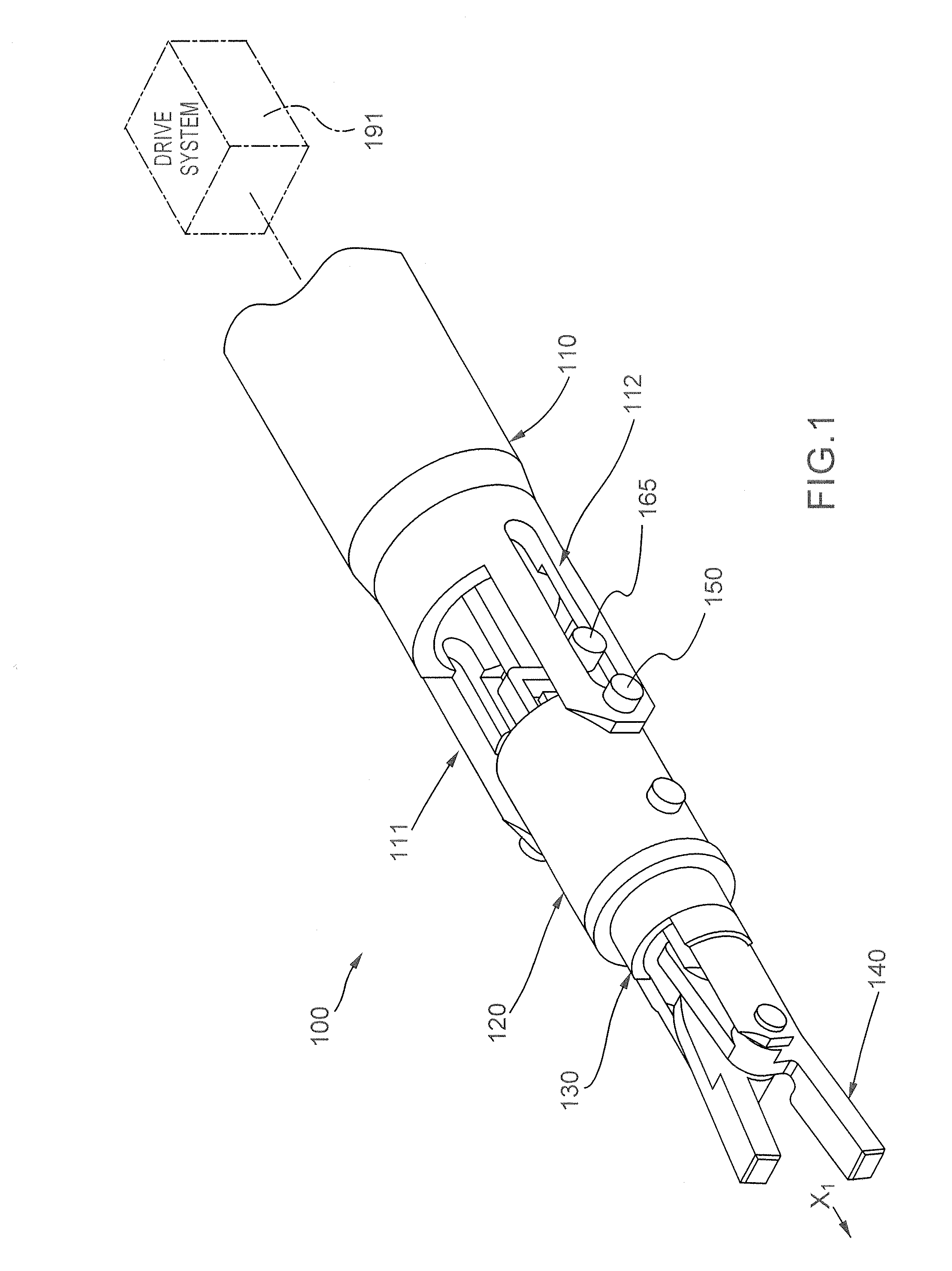
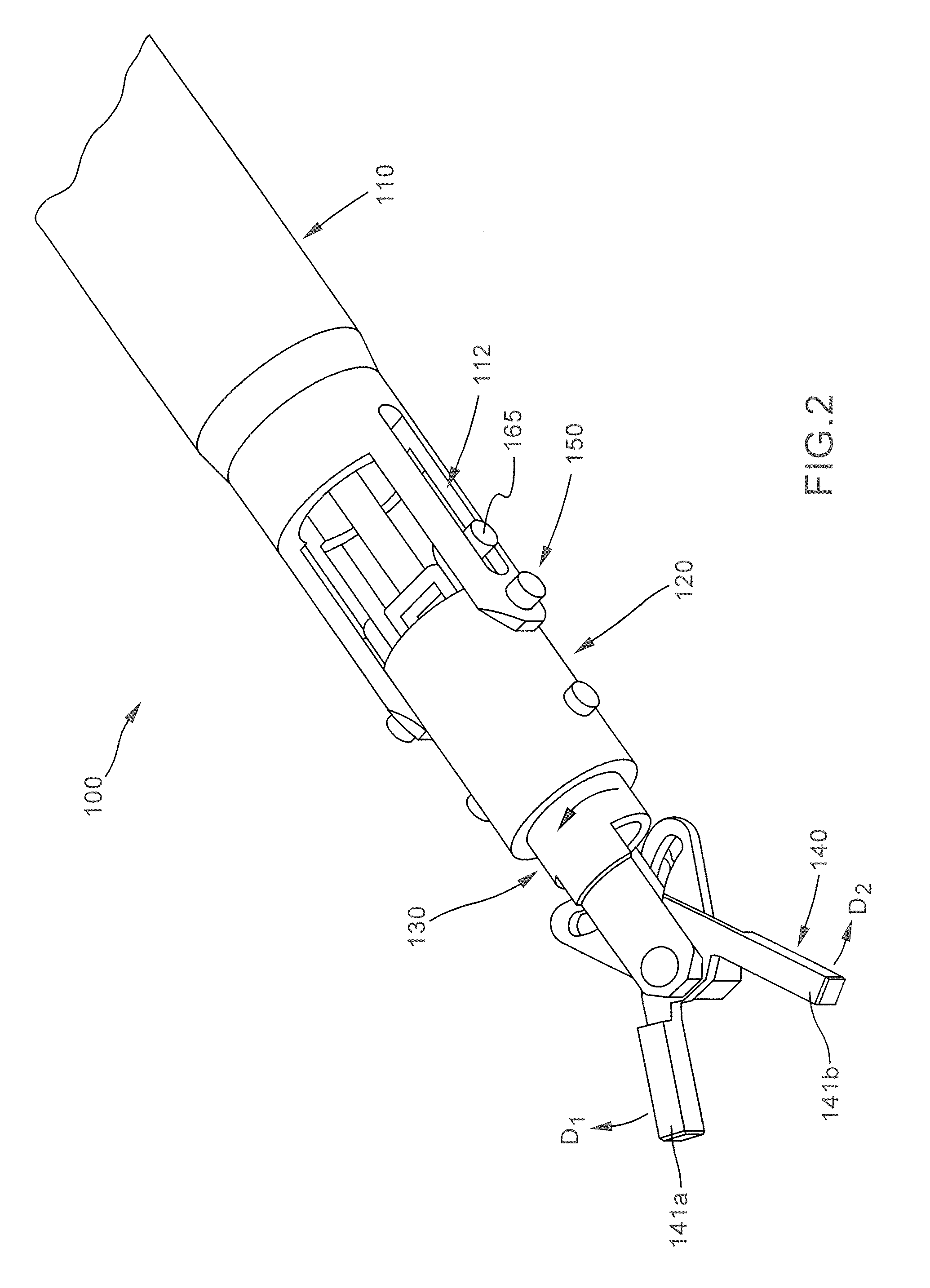
[0053]By way of introduction, aspects of the present invention include a flexible wrist-type element for use in surgical-related activities ...


PUM


Abstract

A flexible wrist-type element and methods of operation thereof, including variations having an angularly moveable hub housing a rotatable and operable end effector driven via a drive train having one or more universal-type joints and / or other flexible couplings moveable via an input mechanism within a housing.

Description

CROSS-REFERENCE TO RELATED APPLICATIONS[0001]This application a continuation-in-part of pending U.S. application Ser. No. 12 / 493,967 entitled “Flexible Wrist-Type Element and Methods of Manufacture and Use Thereof” which is related to applicants' co-pending U.S. patent application Ser. No. 11 / 352,899 titled “HAND-ARTICULATING SURGICAL TOOL” filed Feb. 13, 2006, U.S. patent application Ser. No. 11 / 775,170 titled “SURGICAL TOOL KIT” filed Jul. 9, 2007, and PCT Appl. No. PCT / U.S.07 / 86416 titled “INSTRUMENT POSITIONING / HOLDING DEVICES” filed Dec. 4, 2007, the entirety of each of which is hereby incorporated by reference.BACKGROUND[0002]1. Field of the Invention[0003]Aspects of the present invention relate to a flexible wrist-type element and methods of manufacture and use thereof, including variations having an angularly moveable hub housing and a rotatable and operable end effector driven via a drive train having one or more flexible couplings, such as universal-type joints.[0004]2. Ba...

Claims


Application Information

Patent Timeline
Patent Type & Authority Applications(United States)
IPC IPC(8): A61B19/00B25J17/02B25J15/00B25J13/00
CPCA61B18/1445A61B19/2203A61B2017/00539A61B2017/00544Y10T74/20335A61B2017/2929A61B2017/2936A61B2019/2234A61B2019/2238A61B2017/2927A61B34/30A61B2034/305A61B2034/306
Inventor DOYLE, MARKKOENIG, DONALD H.
Owner CAREFUSION 2200 INC
Why Eureka
Try Eureka