Buoy

a buoy and buoy technology, applied in the field of buoys, can solve the problems of low data rate of buoys designed to operate directly below the surface, limited integration of submarine vessels into naval surface operations, and risk of submarine location detection, and achieve the effect of increasing the protection of electronic equipmen

Active Publication Date: 2011-01-06
BABCOCK IP MANAGEMENT NUMBER ONE LTD
View PDF21 Cites 10 Cited by
  • Summary
  • Abstract
  • Description
  • Claims
  • Application Information

AI Technical Summary

Benefits of technology

[0020]An upper end of the buoy may have a waisted region. The buoy and the waisted region are preferably so arranged that that the waisted region acts, in use when the buoy is floating at the water surface and electronic equipment is operating at the upper end of the buoy, to increase the protection of such electronic equipment from water wash...

Problems solved by technology

The integration of submarine vessels into naval surface operations has been limited by the lack of reliable high-bandwidth data communications systems.
Towed buoy systems can generate surface wake potentially risking detection of the location of the submarine.
Buoys designed to operate directly below the surface suffer from low data rates.
However, in rough waters there may be interruptions to the communications window caused as a result of water washing over the antenna.
A buoy which is designed so that it floats in a stable and generally upright manner at the surface of the water generally has a shape and/or mass distribution such that it is not very well suited to travel...

Method used


Image

  • Buoy
  • Buoy
  • Buoy

Examples


first embodiment

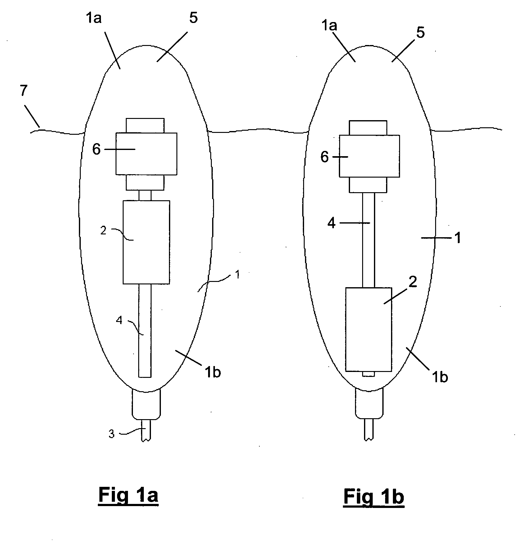
[0039]FIGS. 1a and 1b show as cross-sectional views a buoy 1 according to the present invention. The buoy 1 has a main body 5 which accommodates various components including communications equipment, batteries and the like. The buoy 1 is shown in FIGS. 1a and 1b in a floating position, such that the buoy is in a generally upright orientation with an upper end 1a containing an antenna (not shown) being supported about the water line 7. Inside the buoy 1 there is located a moveable mass 2 which is movable along a longitudinal screw 4 by means of a motor 6. The mass 2 comprises heavy payload components such as batteries and optical conversion equipment. The mass (dry weight) of the buoy 1 is about 24 Kg and the mass of the moveable mass 2 is about 8 Kg. In a modification of this embodiment, the mass of the buoy is 35 Kg, the moveable mass being about 12 Kg.

[0040]The mass 2 is moveable between (i) a first position (shown in FIG. 1b), in which the centre of mass of the buoy is off-set fr...

second embodiment

[0045]In a modification of the second embodiment, the movable mass is fixed and the motor is removed such that the centre of mass of the buoy may be changed only by means of allowing the bladder to expand and contract as previously described.

[0046]A further additional or alternative modification to the second embodiment would be to control actively the contraction and expansion of the bladder. For example, a heater could be provided to heat fluid within a reservoir which would expand to fill and expand the bladder as and when required. Pumps or the like could additionally, or alternatively, be used to inflate and / or deflate.

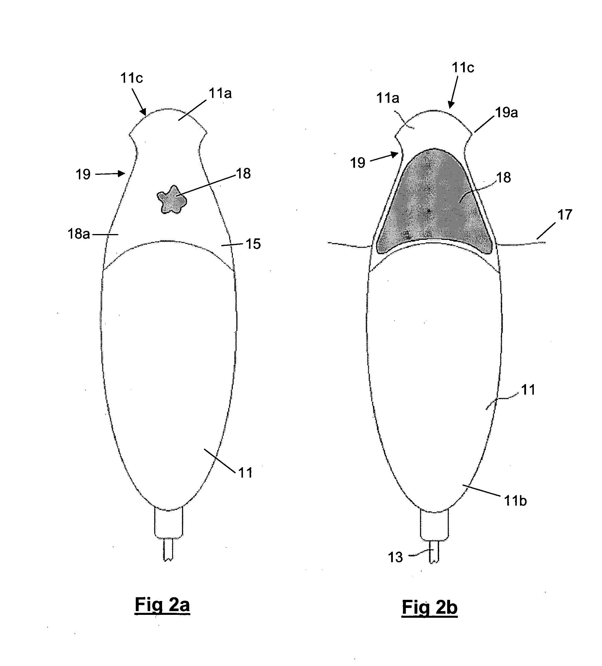
[0047]It will be appreciated, that the shape of the buoy 11 of the second embodiment including the waisted region 19 could by itself provide advantages over conventional shapes of communications buoys, irrespective of whether or not the moveable mass, expandable bladder or other ballasting systems are provided.

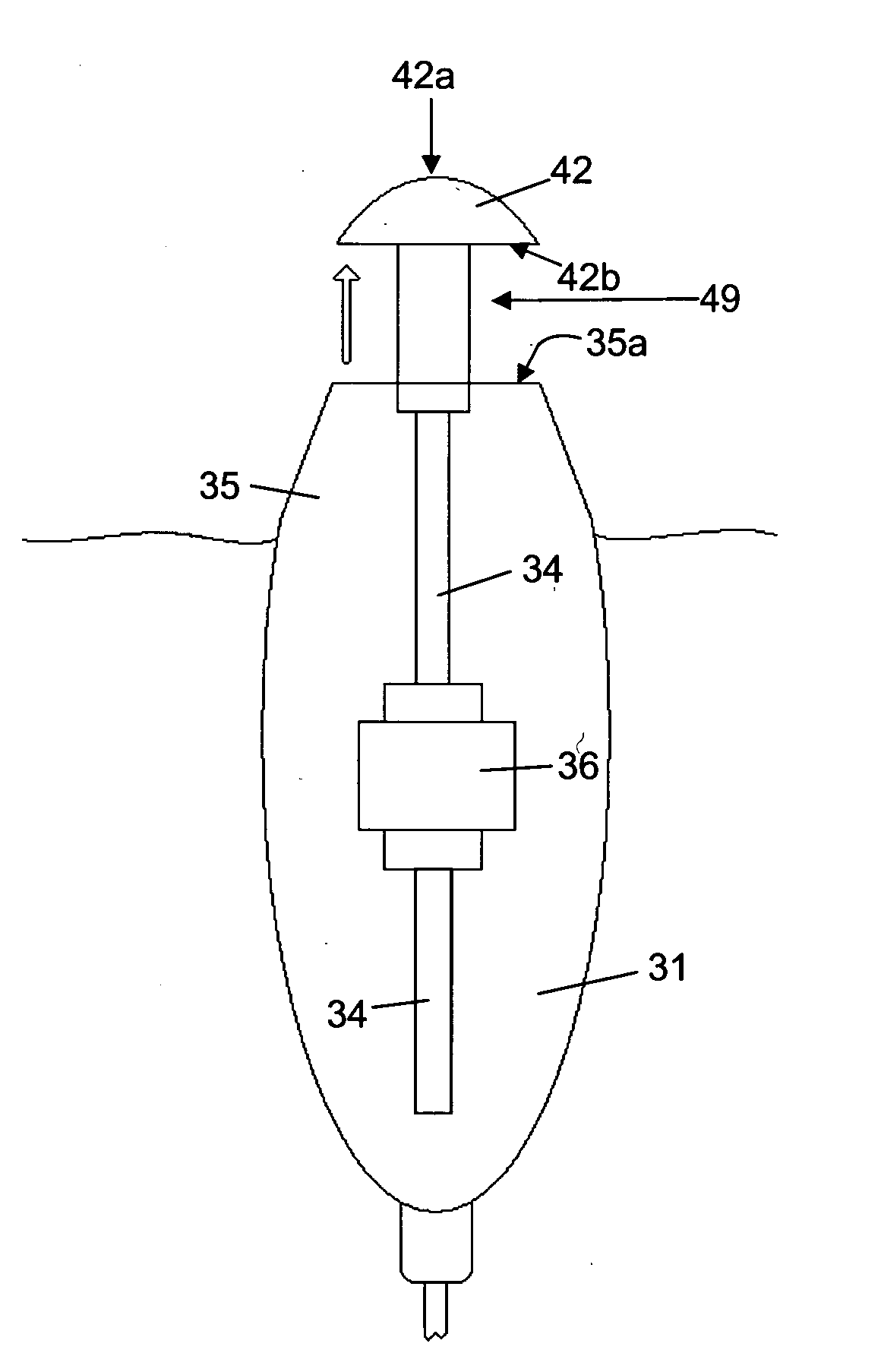
[0048]FIGS. 3a and 3b show in cross-section a buoy 31...


PUM


Abstract

A buoy (1) has a main body (5), and a moveable mass (2) positioned inside the main body. The buoy (1) may be tethered to a submarine vessel and used as a communications buoy. The buoy (1) may be configured for floating in a generally upright orientation at the water surface (7) in a position ready for communication, when the mass (2) is in a first position (FIG. 1a) in which the centre of mass is offset from the centre of buoyancy to improve stability in the water. The buoy (1) may be configured for being towed underwater at speed, when the mass (2) is in a second position (FIG. 1b), in which the centre of mass is closer to the centre of buoyancy, to improve towing stability in the water, thereby allowing the buoy (1) to be towed with its long axis substantially aligned with the direction of motion, thereby reducing wake/plume in the water.

Description

BACKGROUND OF THE INVENTION[0001]The present invention concerns a buoy. More particularly, but not exclusively, this invention concerns a tethered communications buoy for use with a submarine vessel. The invention also concerns a method of recovering a tethered buoy.[0002]The integration of submarine vessels into naval surface operations has been limited by the lack of reliable high-bandwidth data communications systems. Such communications systems should preferably not affect the submarine's primary attribute of stealth, and should preferably be available at speed and depth and without limiting the maneuverability or performance of the submarine vessel.[0003]Proposals for communication systems for a submarine include the use of a tethered communications buoy system. Some of those systems operate by deploying and recovering a communications buoy from a submerged submarine via a tether line, which may for example include a fibre optic cable. Towed buoy systems can generate surface wa...

Claims


Application Information

Patent Timeline
IPC IPC(8): B63G8/00H01Q1/34B63B22/18B63G8/42
CPCB63B22/20
Inventor JONE, TIMOTHY MEALLEWHITTEN, TIMOTHY JAMES
Owner BABCOCK IP MANAGEMENT NUMBER ONE LTD
Why Eureka
Try Eureka