Tubular article

a technology of tubular articles and tubes, applied in the field of tubular articles, can solve the problems of reducing the wall thickness of the rib, affecting the structural integrity of the article itself, and jeopardizing the integrity of the tubular article itself, so as to reduce or even suppress the undesirable effects

Inactive Publication Date: 2011-01-06
ITI SCOTLAND
View PDF11 Cites 2 Cited by
  • Summary
  • Abstract
  • Description
  • Claims
  • Application Information

AI Technical Summary

Benefits of technology

[0009]The present invention aims to provide a multi-layered tubular article obtained by helically winding a single self-overlapping strip of material for use particularly, but not exclusively, in the gas, oil or chemical industry in which the design of the strip has been modified with regards to the prior art in order to reduce or even suppress the undesirable effects known therein.
[0010]According to one aspect of the present invention there is provided, one or more strips of self overlapping helically-wound material, wherein said strip includes a first flat portion at a first inner diameter D1, a second flat portion at a second outer diameter, a first step portion and a second step portion each spaced from the other across a width of said strip, wherein said first step portion is located between said first and second flat portions and comprises a curved step having an outer diameter greater than said second diameter and a first radius of curvature wherein said second step portion is located at an otherwise free end of said second flat portion and comprises a curved step having a second radius of curvature and wherein said second radius of curvature (R6, R8) is greater than said first radius of curvature such as to allow said second step portion to overlap said first step portion. The curved step combines the functionality of a step or joggle and a rib allowing the formation of a multi-layered tubular structure having a low concentration of material stress within the joggle whilst also providing the functionality of the rib whilst preserving the axial properties and radial load carrying capabilities as well as retaining the helical screw-thread shape. The curved step offers a smoother and more rounded discontinuity of the material mainly provided by a longer radius of curvature which results in less localised axial stresses. Consequently, the use of higher strength material may now be contemplated and the applications of such tubular structure may be extended.

Problems solved by technology

The deformation required is likely to result in the formation of localised points of stress along its length, which may lead to microscopic cracks which could potentially propagate and, therefore, jeopardise the integrity of the tubular article itself.
Unfortunately, this arrangement also relies on a joggle between the rib portions and the edges of the strip terminate short of the rib portions, thereby reducing the wall thickness within the rib, which is clearly very undesirable as it will have a detrimental affect on the structural integrity of the article itself.
In addition to the above, the discontinuities created by the overlap of the strip edges occurring at the joggle-step, which is usually located at mid-distance between two consecutive ribs, are areas of possible high localised axial stresses which are likely to be detrimental to the overall stability of the helically wound tubular structure.
Unfortunately, this arrangement only lends itself to the formation of a mono-layered tubular structures and the interlock / rib portion includes sharp edges and must be of a very flexible material if the interlocking portions are to engage with each other.
This arrangement might not lend itself to use at elevated pressures and would be difficult to form from high tensile material.
Such an arrangement may also be described as an unbalanced structure in that it is generally mono-layered and then overlaps simply at the edges of the strip.

Method used


Image

  • Tubular article
  • Tubular article
  • Tubular article

Examples


Embodiment Construction

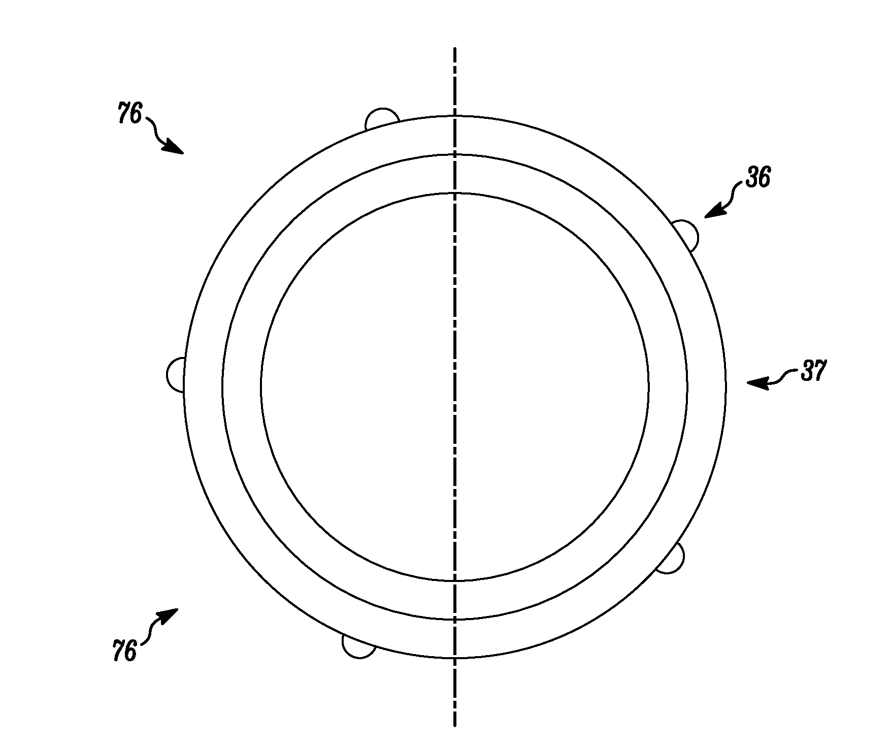
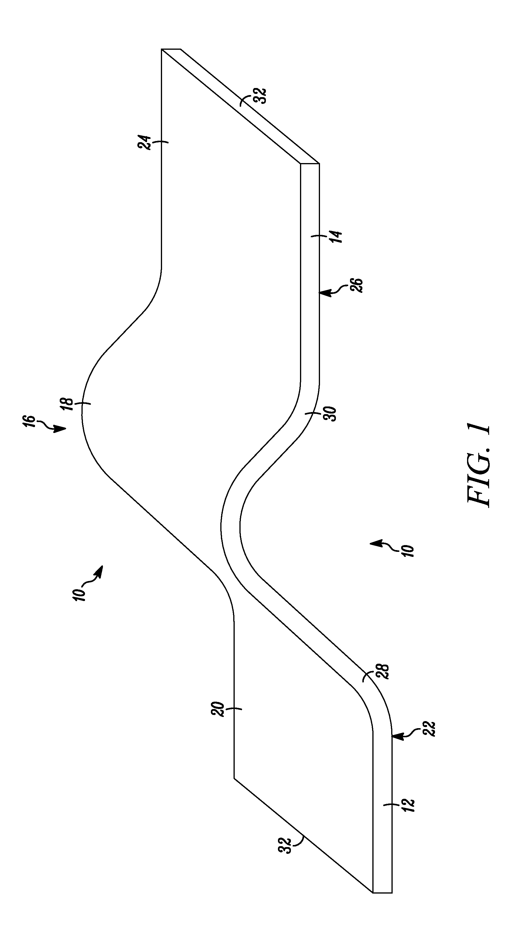
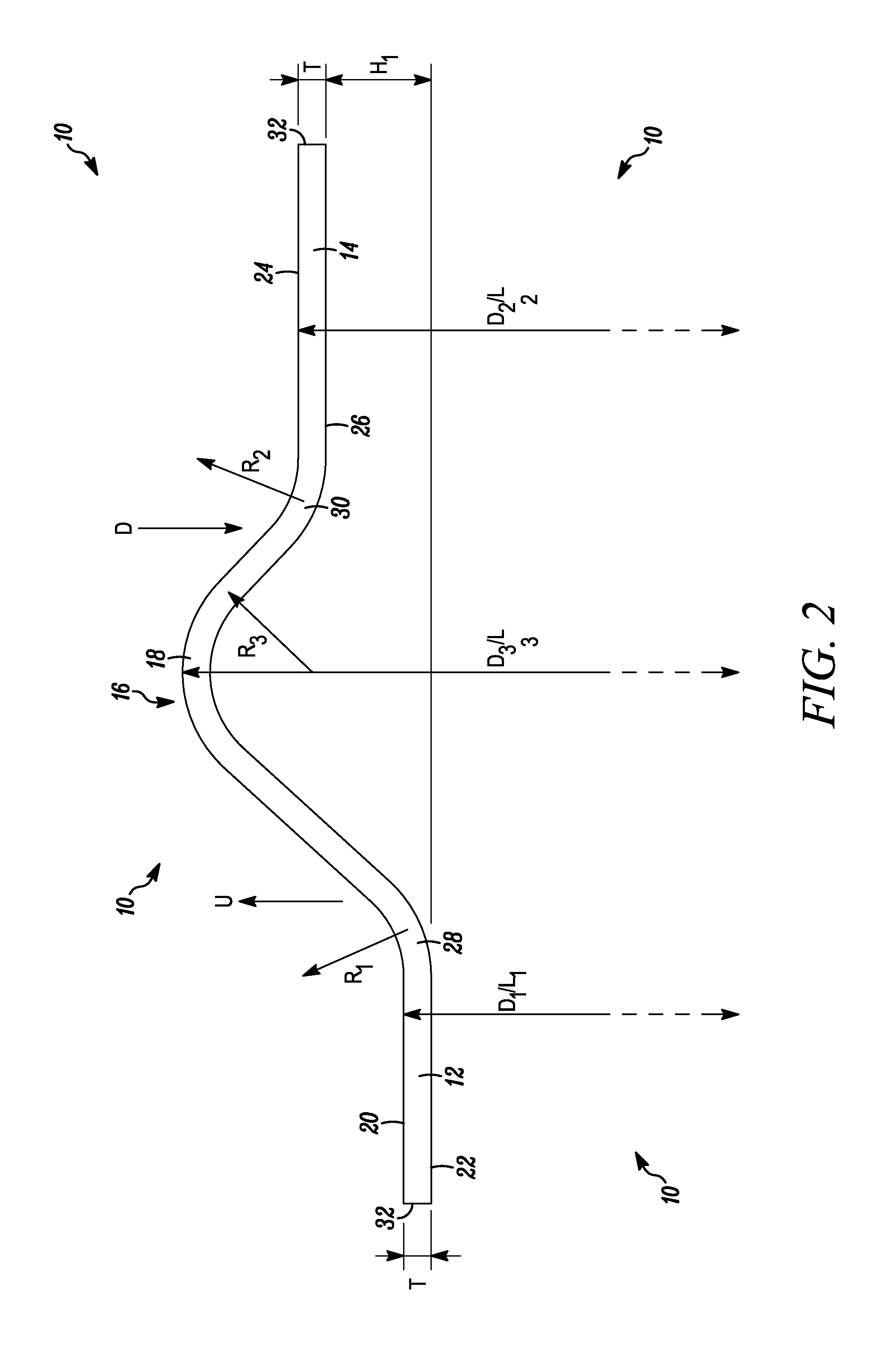
[0038]Referring now to the drawing in general but particularly to FIGS. 1 and 2, a strip 10 of material, such as metal, has a thickness T and includes a first flat portion 12 at a first inner diameter D1 orlevel L1 and a second flat portion 14 at a second outer diameter D2 or level L2 and a step portion 16 therebetween. The step portion 16 comprises a curved step 18 rising first upwardly in the direction of arrow U and then downwardly in the direction of arrow D and having an outer diameter D3 or level L3 greater than said second outer diameter D2 orlevel L2. This step portion effectively creates the joggle and the rib of the prior art whilst reducing the severity of bending associated with the prior art joggle and thereby reducing the localised stressing of the material. Said first flat portion 12 comprises a top surface 20 and a bottom surface 22, and, in the same manner, said second flat portion 14 also comprises a top surface 24 and a bottom surface 26. The surfaces of the first...


PUM

PropertyMeasurementUnit
inner diameter D1aaaaaaaaaa
outer diameter D2aaaaaaaaaa
outer diameter D3aaaaaaaaaa

Abstract

The present invention provides a strip and a tubular article formed from said strip which may, for example, be used in the oil and gas industry for transporting fluids which may be volatile fluids or corrosive fluids and which may be at elevated temperatures and / or pressure. The strip includes a plurality of combined step (joggle) and rib arrangements. In the finished assembled article, the strip is wound in helically self-overlapping relationship such as to allow corresponding step portions to sit one within the other. The step effectively provides the dual function of a joggle and a rib as known in the art and does so in a manner that reduces the forming stresses in the material and increases the strength of the final article.

Description

CROSS-REFERENCE TO RELATED APPLICATIONS[0001]This application is a United States national phase application under 35 U.S.C. §371 of International Patent Application No. PCT / BG2009 / 050008, filed on Jan. 7, 2009, and claims the benefit of Great Britain Patent Application No. 0800256.0, filed on Jan. 8, 2009, both of which are incorporated by reference herein. The International Application was published as International Publication No. WO 2009 / 087415 A1 on Jul. 16, 2009.FIELD OF THE INVENTION[0002]The present invention relates to a tubular article and relates particularly, but not exclusively, to a substantially rigid tubular article suitable for use in gas and fluid transportation by the oil and gas industry and being made from at least one strip of self overlapping helically-wound material. Such an arrangement may be used in the production of parallel or tapered elongate tubes and the like.BACKGROUND[0003]U.S. Pat. No. 3,530,567 describes the formation of multi-layered tubular struct...

Claims


Application Information

Patent Timeline
Patent Type & Authority Applications(United States)
IPC IPC(8): F16L9/16B32B3/00B65D85/00
CPCB21C37/122F16L9/045Y10T428/24628F16L11/16F16L9/165B21C37/12B29C53/78F16L9/16
Inventor BOOTH, JOHN PETER
Owner ITI SCOTLAND
Why Eureka
Try Eureka