Method and welding device for the evaluation of the welding current intensity during the welding of container bodies

Active Publication Date: 2011-01-06
SOUDRONIC
View PDF10 Cites 64 Cited by
  • Summary
  • Abstract
  • Description
  • Claims
  • Application Information

AI Technical Summary

Benefits of technology

[0010]In case of a further preferred embodiment it is verified, preferably automatically, if the welding current intensity used for the production series lies within the preferred range or if it has the exact preferred value, and if this is not the case, a new welding current intensity is set by the controller, preferably also automatically, which is th

Problems solved by technology

On the contrary, if the welding current intensity during the test welding was set too high, the welding takes place with a too high temperature and craters are

Method used


Image

  • Method and welding device for the evaluation of the welding current intensity during the welding of container bodies
  • Method and welding device for the evaluation of the welding current intensity during the welding of container bodies
  • Method and welding device for the evaluation of the welding current intensity during the welding of container bodies

Examples


Example

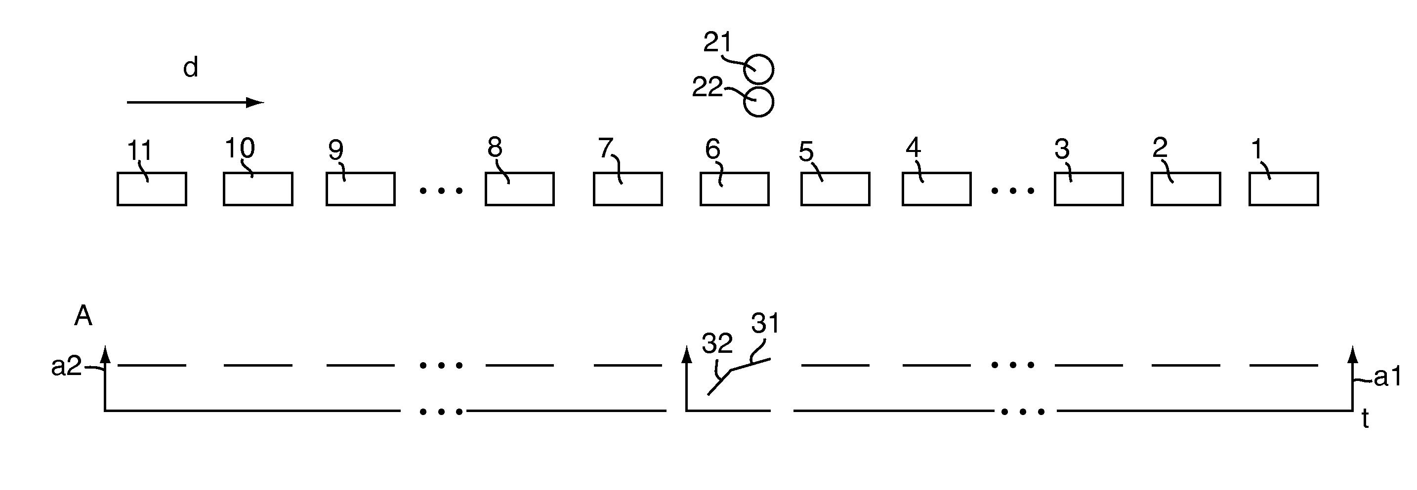
[0023]FIG. 1 shows schematically a sequence of container bodies 1 to 11 of a production series of container bodies. The container bodies are welded for example on a resistance welding machine according to FIG. 4, of which only the welding rollers 21 and 22 are shown in FIG. 1. The single container bodies are fed as body blanks from a rounding device into the welding device and travel through it in the direction of arrow d. Thus, the container body blanks 11 to 7 upstream of the welding rollers are not yet welded in the schematic view of FIG. 1, the container body is just being welded and the container bodies 5 to 1 downstream of the welding rollers have already been welded.

[0024]The welding of the series of container bodies 1 to 5 has been carried out in a known way with a substantially constant welding current intensity. The welding current as a function of time is shown in a rough schematic way below the container bodies. The vertical axis denotes the welding current intensity in ...


PUM

PropertyMeasurementUnit
Temperatureaaaaaaaaaa
Electric energyaaaaaaaaaa
Currentaaaaaaaaaa

Abstract

In order to evaluate the welding current for the resistance seam welding of an overlap seam of container bodies, a welding with changing welding current intensity is carried out for a container body of the production series, resulting in a changing welding of the seam, ranging from the welding with a too high temperature to the welding with a too low temperature. The electric energy for this welding is determined several times during this welding and/or the temperature of the weld seam is determined several times and the welding current intensity is determined at which the welding of the individual container body is too cold and the welding current intensity at which the welding is too hot. This determination is based on the determined electric energy values and/or on the determined temperature values and based on this determination a preferred range for the welding current intensity within these limits of too hot and too cold is determined. By this, an evaluation if the welding current intensity is correct may take place in a simple way during the production. After the welding of the individual container bodies a changed welding current intensity lying between the welding current intensity of the too hot and of the too cold welding may optionally be set and used for the following series of container bodies of the production series.

Description

CROSS REFERENCE TO RELATED APPLICATIONS[0001]This application claims the priority of Swiss patent application 1027 / 09, filed Jul. 2, 2009, the disclosure of which is incorporated herein by reference in its entirety.BACKGROUND[0002]The invention relates to a method for evaluating the applied welding current intensity during electrical resistance seam welding of overlap seams of consecutive container bodies of a production series. Furthermore, the invention relates to a welding device for the resistance seam welding of container bodies, comprising welding rollers, a welding current generator and a welding current controller, as well as an installation for the multiple detection along the welding seam of a container body of the electrical energy brought into the welding seam and / or for the multiple detection of the temperature of the welding seam of a container body along the welding seam.[0003]Furthermore, the invention is related to a method and a welding device for welding container...

Claims


Application Information

Patent Timeline
IPC IPC(8): B23K11/06B23K11/24
CPCB23K11/063B23K2201/125B23K31/125B23K11/0876B23K11/25B23K2101/125
Inventor MUELLER, WILLIDIETRICH, DANIEL
Owner SOUDRONIC
Why Eureka
Try Eureka