Telescoping and sweeping wing that is reconfigurable during flight

Inactive Publication Date: 2011-01-06
SKILLEN ROBERT STEWART +2
View PDF8 Cites 58 Cited by
  • Summary
  • Abstract
  • Description
  • Claims
  • Application Information

AI Technical Summary

Benefits of technology

[0012]It is an object of the present invention, therefore, to provide an aircraft wing that is sufficiently versatile to encourage and facilitate wider use of dual-mission or multi-mission aircraft, by

Problems solved by technology

This diversity of design therefore requires engineering tradeoffs or compromises between conflicting demands for payload, speed, altitude, and endurance.
The need for two different interchangeable wings, however, has major drawbacks, namely flexibility and reaction time.
Nor does such an interchangeable wing concept allow the military to

Method used


Image

  • Telescoping and sweeping wing that is reconfigurable during flight
  • Telescoping and sweeping wing that is reconfigurable during flight
  • Telescoping and sweeping wing that is reconfigurable during flight

Examples


Embodiment Construction

[0048]The present invention will now be described more fully with reference to the accompanying drawings, in which preferred embodiments of the invention are shown. The invention may, however, be embodied in many different forms and should not be construed as being limited to the embodiments set forth herein; rather, these embodiments are provided so that this disclosure will be thorough and complete, and will fully convey the concept of the invention to those skilled in the art.

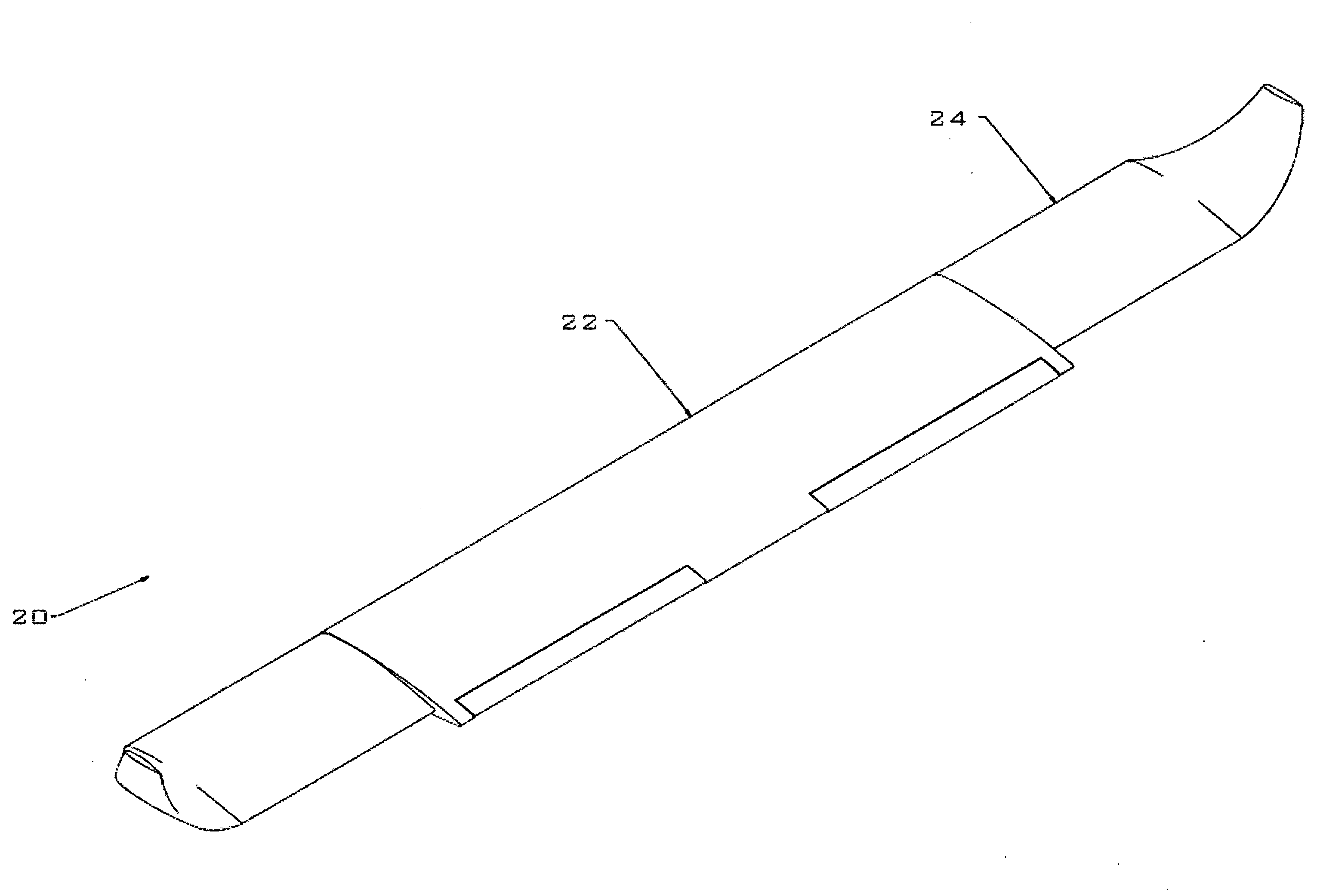
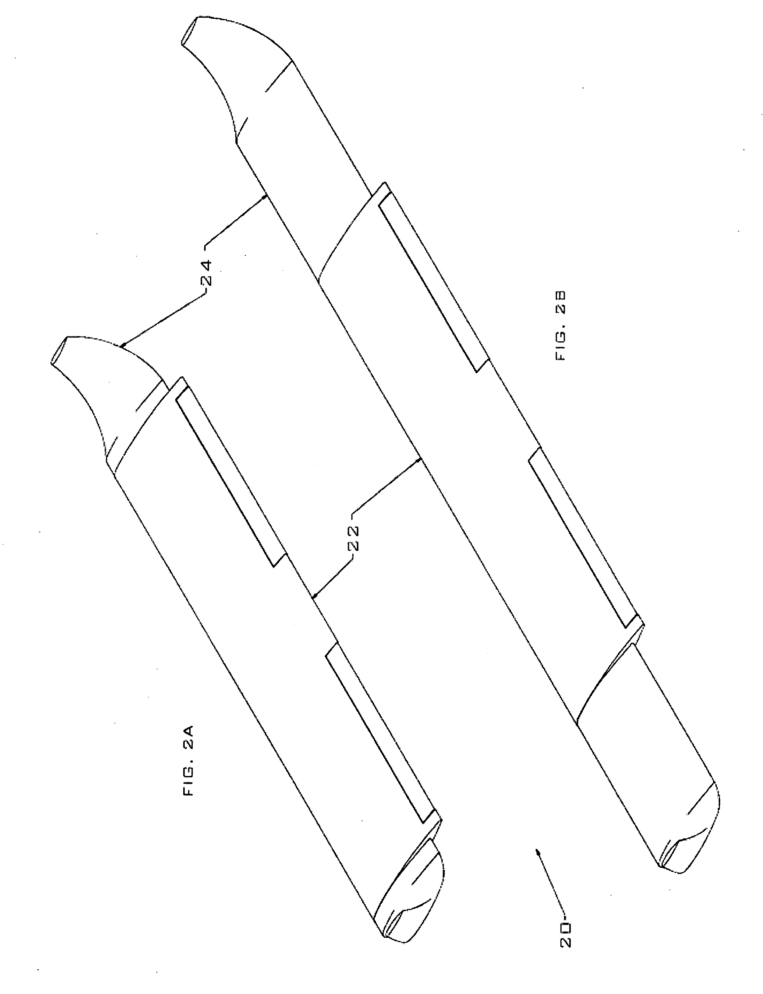
[0049]FIGS. 2A and 2B show an aircraft wing 20 in accordance with the invention, comprising an airfoil shaped root section 22 and an airfoil shaped telescoping end section 24. It is apparent that in FIG. 2A, the telescoping end 24 is retracted within the root section 22, and in FIG. 2B, the telescoping end 24 is extended from the root section 22. While the telescoping end 24 slides or moves back and forth within the root section 22 as shown in FIGS. 2A and 2B, one of skill in the art would understand that th...


PUM


Abstract

An aircraft wing includes a stationary root section and a telescoping end section slideable in the span wise direction, where the loads for the root and extendable end sections are carried predominately by the airfoil composite skins, rather than a framework of spars and ribs as in conventional aircraft wings. In a single-telescoping configuration the telescoping end section slides within the root section as it extends and retracts during flight, and in another, the telescoping end section slides over the root section as it extends and retracts during flight. The aircraft wing can also include a second telescoping distal end section, and can sweep back during flight, while the end sections or distal end sections are extended or retracted.

Description

RELATED APPLICATIONS[0001]This application claims priority to U.S. patent application Ser. No. 61 / 006,082, filed Dec. 18, 2007, and U.S. patent application Ser. No. 61 / 136,263, filed Aug. 22, 2008, the entire contents of which are hereby incorporated herein by reference in their entirety.BACKGROUND OF THE INVENTION[0002]1. Field of the Invention[0003]The present invention relates generally to aircraft wings for manned and unmanned air vehicles, and more particularly to an aircraft wing with a stationary root section and at least one telescoping end section slideable relative to the root section, which can be reconfigured (extended or retracted) during flight. The aircraft wing can also sweep back during flight, while the telescoping end sections are extended or retracted.[0004]2. Description of the Related Art[0005]Aircraft are employed in a variety of roles, such as cargo and passenger carrying, reconnaissance, surveillance, or for delivering a payload in the form of munitions or m...

Claims


Application Information

Patent Timeline
IPC IPC(8): B64C3/54B64D37/04
CPCB64C3/40B64C3/54B64C39/024B64D37/14B64C2201/102B64C2201/121B64C2201/127B64C2201/021B64U10/25B64U30/12B64U2101/15B64U2101/30
Inventor SKILLEN, ROBERT STEWARTJONES, RAYMOND CHARLESJONES, ROSS MICHAEL
Owner SKILLEN ROBERT STEWART
Why Eureka
Try Eureka