
Anti-leak valve unit for overtube

a valve unit and valve valve technology, applied in the field of anti-leak valve units for overtubes, can solve the problems of affecting the operation of the operator, so as to achieve the effect of convenient attachment and removal

Inactive Publication Date: 2011-01-06
SUMITOMO BAKELITE CO LTD
View PDF18 Cites 13 Cited by
  • Summary
  • Abstract
  • Description
  • Claims
  • Application Information

AI Technical Summary

Benefits of technology

[0009]The present invention provides an anti-leak valve unit that allows easily extracting a resected diseased tissue from a body cavity in an endoscopic resection such as EMR and ESD, and that prevents leakage of air supplied into the body cavity, despite moving the endoscope in any direction with respect to the overtube.
[0031]The present invention provides an anti-leak valve unit for overtube that allows extracting a diseased tissue without damaging the same in endoscopic mucosal resection, and preventing leakage of supplied air despite a back and forth or rotational movement of the endoscope, and that can be easily attached and removed to and from the overtube.

Problems solved by technology

Accordingly, a gap is prone to be formed between the valve element of the anti-leak valve attached to the base end portion of the overtube and a proximal end portion of the endoscope.
The formation of the gap between the valve element of the anti-leak valve and the endoscope incurs the problem that the air supplied into the body cavity leaks through the gap and the body cavity is thereby deflated, which degrades the visual field of the endoscope.
Also, in the case where the air supply to the part to be treated is insufficient, the part cannot be sufficiently inflated, which may make it difficult for the operator to execute the procedure.
However, since the endoscope insertion port of the anti-leak valve is relatively small, the extraction of the diseased part with the anti-leak valve attached to the overtube is technically difficult, especially in the case of ESD.
More particularly, because of the presence of the anti-leak valve attached to the base end portion of the overtube, the diseased tissue is damaged when the endoscope passes through the anti-leak valve, or the extraction of the entirety of the diseased tissue is disabled.

Method used


Image

  • Anti-leak valve unit for overtube
  • Anti-leak valve unit for overtube
  • Anti-leak valve unit for overtube

Examples


first modification

[0096]FIG. 7 is a cross-sectional view of the anti-leak valve unit 1 according to a first modification of this embodiment. As shown therein, the anti-leak valve unit according to this modification includes a second valve element 51 having a second endoscope insertion port 61 and a second elastic portion 81, and located on the distal end side of the valve element (first valve element 5), with a spacing therefrom.

[0097]The second valve element 51 is pressed against the first valve element 5 by a second fixing ring 71, so as to be retained therebetween.

[0098]Providing thus the second endoscope insertion port 61 allows further assuring the air-tightness between the endoscope and the endoscope insertion port 6. In this case, increasing the thickness of the first fixing ring 7 between the first valve element 5 and the second valve element 51 from the foregoing embodiment (ref. FIG. 5) thereby defining a larger space between the first valve element 5 and the second valve element 51 prevent...

second modification

[0100]FIG. 8 is a cross-sectional view of the anti-leak valve unit 1 according to a second modification of the foregoing embodiment. As shown therein, in the elastic portion 8 a hill portion and a valley portion (folded portion 82) of the bellows portion may be made thinner than the remaining straight portion (slope portion 83). Such configuration permits the bellows portion to contract and stretch more flexibly thereby reducing friction with the endoscope when inserting, removing and manipulating the same, which further upgrades the manipulability of the endoscope.

[0101]The endoscope is manipulated so as to axially rotate in the endoscope insertion port 6, in addition to movements in the back and forth, up and down, and left and right directions with respect to the endoscope insertion port 6. In this case, against the axial rotational motion in the endoscope insertion port 6, the high elasticity of the thicker slope portion 83 of the bellows portion prevents the endoscope insertion...

third modification

[0105]FIG. 9 is a cross-sectional view of the anti-leak valve unit 1 according to a third modification of the foregoing embodiment.

[0106]In the anti-leak valve unit 1 according to this modification, the endoscope insertion port 6 includes a straight tube portion 65 extending thicknesswise of the valve element 5.

[0107]The anti-leak valve unit 1 according to this modification is different from that of the foregoing embodiment (ref. FIG. 5) in that the endoscope insertion port 6 is closely fitted to the outer circumferential surface of the endoscope over a predetermined extended length.

[0108]The reinforcing member 9 of the O-ring shape is formed along the outer periphery of the straight tube portion 65, and the inner circumferential surface of the straight tube portion 65 is of a cylindrical shape.

[0109]The anti-leak valve unit 1 according to this modification enhances the tightness of the contact between the endoscope insertion port 6 and the endoscope, thereby preventing the O-ring s...


PUM


Abstract

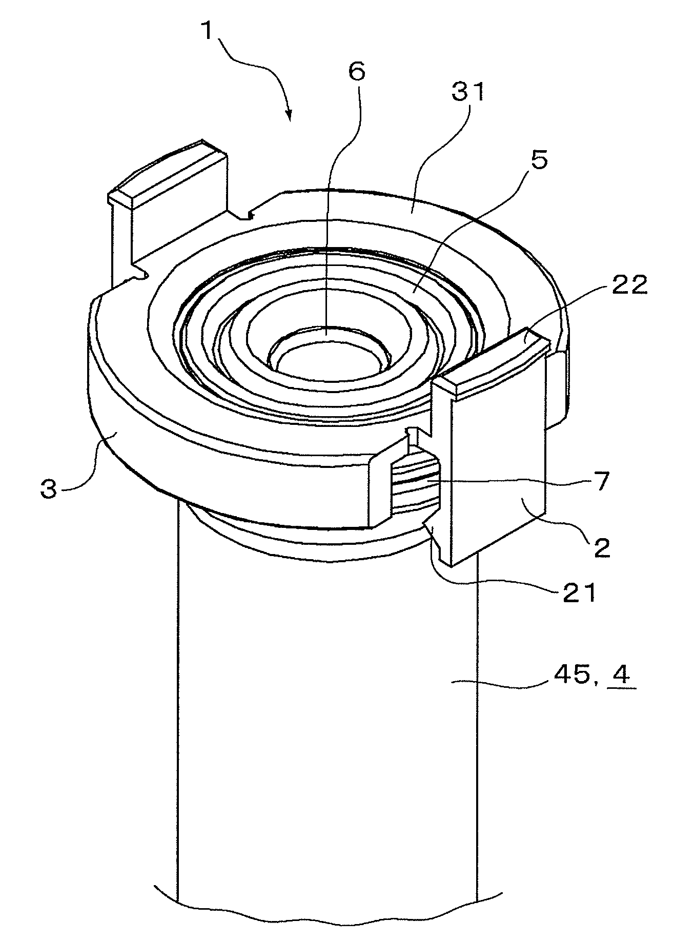
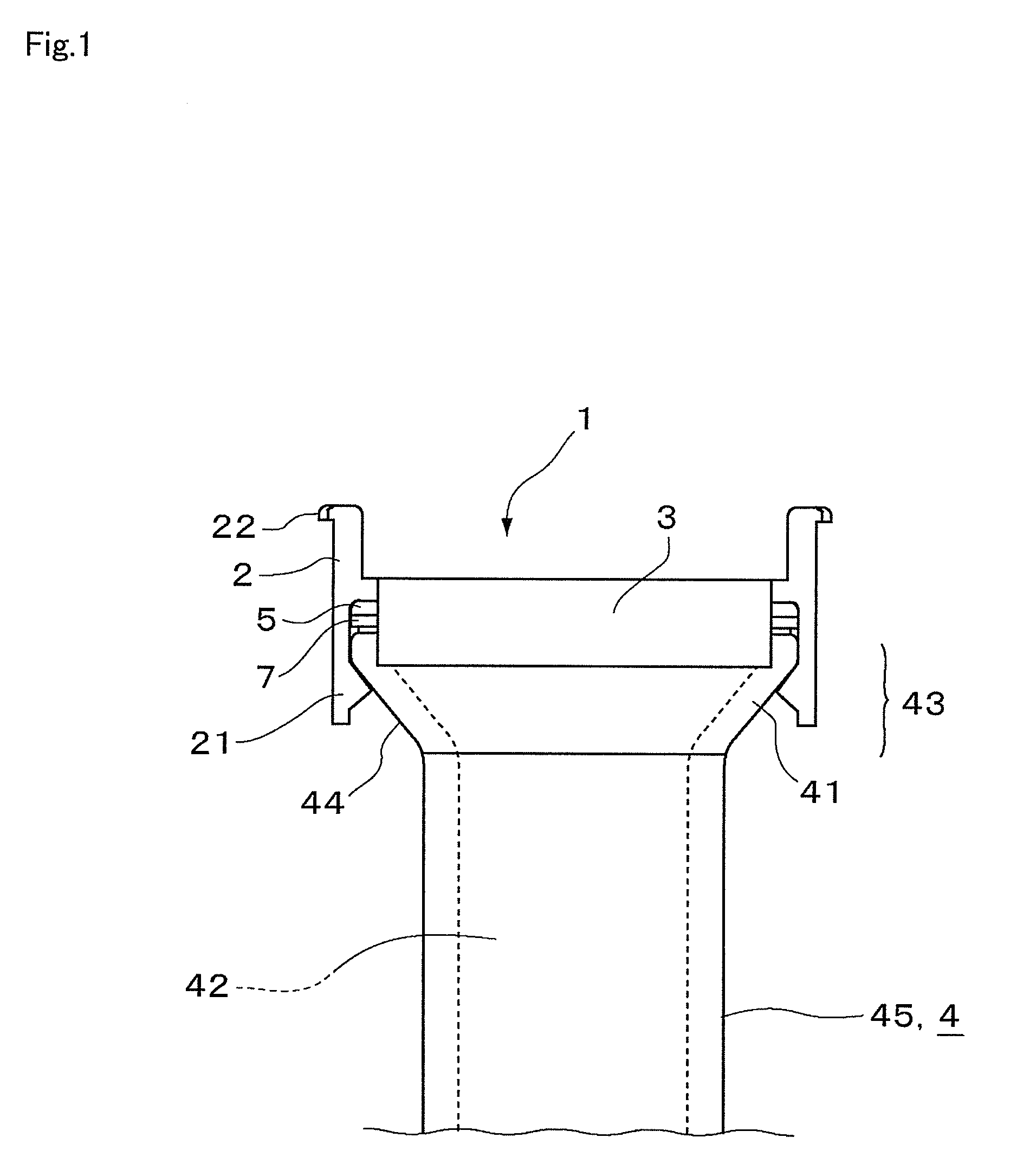
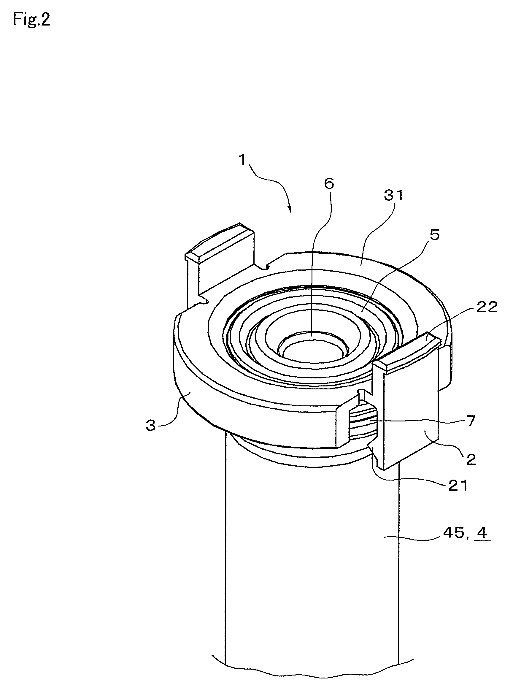
An anti-leak valve unit (1) is removably attached to a base end portion (43) of an overtube (4) that includes an inner cavity (42) through which an endoscope is to be removably inserted, and that is to be inserted into a body cavity. The anti-leak valve unit (1) includes a frame portion (3) attached to an outer circumferential surface (44) of the base end portion (43) of the overtube (4), a fitting device (2) provided on the frame portion (3) so as to be removably engaged with the outer circumferential surface (44) of the base end portion (43), and a valve element (5) provided inside the frame portion (3). The valve element (5) includes an annular endoscope insertion port located at a generally central portion of the valve element (5) so as to be circumferentially fitted to the endoscope, and a flexible elastic portion provided around the endoscope insertion port.

Description

TECHNICAL FIELD[0001]The present invention relates to an anti-leak valve unit for overtube.BACKGROUND ART[0002]The overtube is employed for safely and smoothly inserting and removing an endoscope into and from a body cavity (for example, refer to a patent document 1). Normally, an anti-leak valve is attached to a base end portion of the overtube, in order to prevent leakage of air supplied into the body cavity.[0003]Generally, the anti-leak valve used with the overtube is made of a rubber or silicone rubber that can follow up the movement of the endoscope, and fixed to a portion of the overtube or to a grip (for example, refer to a patent document 2).[0004]In the event of executing Endoscopic Mucosal Resection (EMR) which is an operation of endoscopically resecting a mucous membrane of esophagus, stomach, or colon, conventionally a snare is employed for dividing the diseased tissue in the case where the diseased part is large, and since the diseased tissue that has been resected is ...

Claims


Application Information

Patent Timeline
Patent Type & Authority Applications(United States)
IPC IPC(8): A61B1/00
CPCA61B1/00137A61B1/015A61B1/00154A61B1/00128A61B1/00135A61B1/00112A61B1/0014A61B17/3423
Inventor ASAI, HIDEAKIHARATA, SHINETSUTOYOTA, YOSHIKI
Owner SUMITOMO BAKELITE CO LTD
Learn More