Tool for Use with a Bone Anchor, in Particular for Spinal Surgery

a bone anchor and tool technology, applied in the field of tools for use with bone anchors, can solve problems such as unloaded rod elements, and achieve the effect of facilitating handling

Active Publication Date: 2011-01-06
BIEDERMANN TECH GMBH & CO KG
View PDF38 Cites 49 Cited by
  • Summary
  • Abstract
  • Description
  • Claims
  • Application Information

AI Technical Summary

Benefits of technology

An embodiment of the invention is a tool for use with a bone anchor of the above described type where loads acting onto the bone anchor and therefore onto the bone are reduced and which may allow for a facilitated handling.
A feature of the tool is that the tightening torque which has to be applied manually by the surgeon is considerably reduced. Therefore, the manually-applied fastening torque is small and tightening of the locking screw can be performed smoothly.

Problems solved by technology

This results in an unloaded rod element.

Method used


Image

  • Tool for Use with a Bone Anchor, in Particular for Spinal Surgery
  • Tool for Use with a Bone Anchor, in Particular for Spinal Surgery
  • Tool for Use with a Bone Anchor, in Particular for Spinal Surgery

Examples


Embodiment Construction

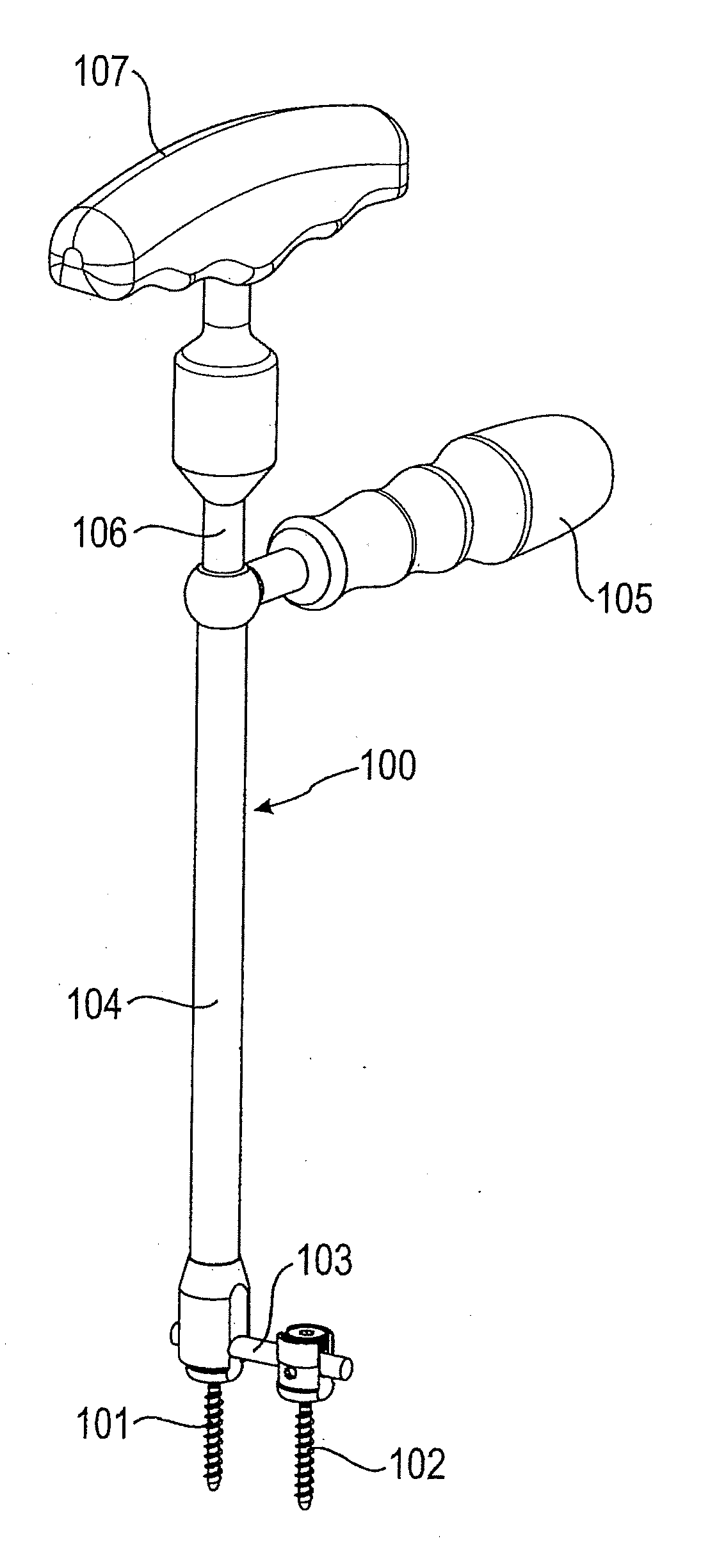
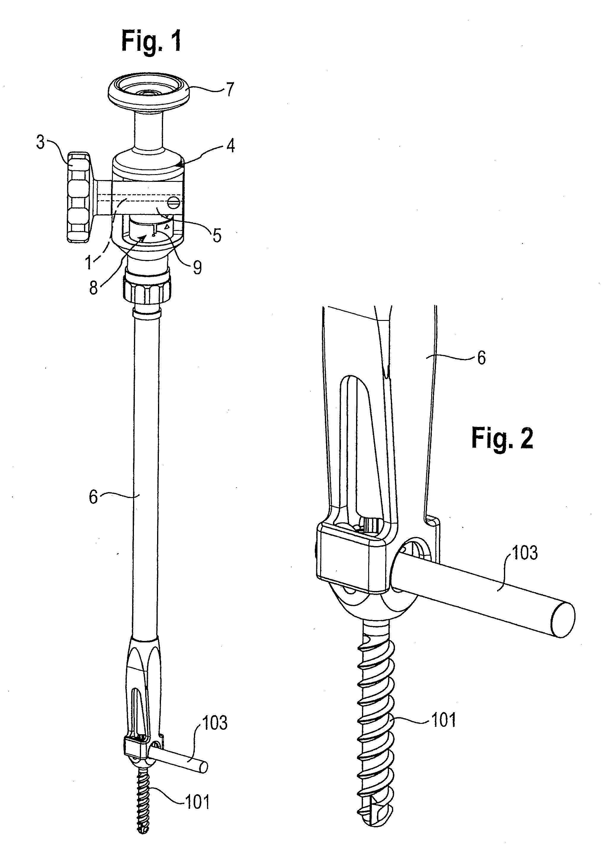
With reference to FIGS. 1 to 5, a tool according to one embodiment comprises a screw driver portion, which includes a drive shaft 1 as schematically shown by the dashed line in FIG. 1 and a driven shaft 2 as shown in FIG. 3. The drive shaft 1 has a handle 3 at its free end projecting outside a housing 4. The drive shaft 1 and the driven shaft 2 enclose an angle of 90° and are connected by a reduction gear unit 5, which will be explained in more detail below.

The tool further comprises a counter-holding portion 6, which is fixedly connected to the housing 4 so that the driven shaft 2 is rotatable with respect to the counter-holding portion 6. At its free end opposite to the counter-holding portion 6, the housing 4 comprises a handle 7 for holding the tool. The central axis of the handle 7 extends substantially perpendicular to the central axis of the handle 3 of the drive shaft 1. This allows a convenient handling of the counter-holding portion.

The tool further has a display member 8,...


PUM


Abstract

A tool is provided for use with a bone anchor, wherein the bone anchor has an anchoring section and a receiving portion for receiving a rod to be connected to the anchoring section and a locking element, the tool comprising a tip portion for engaging the locking element; a mechanism to apply torque to the tip portion comprising a drive shaft and a driven shaft coupled by a gear unit, where the drive shaft has a different axis than the driven shaft, and where the driven shaft comprises an engagement portion configured to connect the driven shaft to the gear unit; and a counter-holding portion for engaging the receiving part, wherein the counter-holding portion is rotatable with respect to the tip portion.

Description

BACKGROUNDThe invention relates to a tool for use with a bone anchor. The bone anchor includes an anchoring section and a receiving part for receiving a rod to be connected to the anchoring section and a locking element. The tool is particularly applicable in spinal surgery, for example for the fixation of a rod to pedicle screws.A known tool 100 is shown in FIGS. 19 and 20 in connection with polyaxial screws 101 and 102, which are connected via a rod 103. The tool 100 includes a counter-holding portion 104 with a handle 105 and a screw driver portion 106. The screw driver portion 106 is rotatable with respect to the counter-holding portion 104 and also comprises a handle 107. The screw driver portion 106 has a tip portion (not shown) that engages a locking screw 108 of the polyaxial screw 101 for fixation of the rod 103 within the receiving portion 109. The counter-holding portion 104 engages the receiving portion 109 and holds the receiving portion during tightening of the locking...

Claims


Application Information

Patent Timeline
Patent Type & Authority Applications(United States)
IPC IPC(8): A61B17/58
CPCA61B17/7091A61B2019/464A61B2019/301A61B17/7082A61B17/8875A61B2090/031A61B2090/064B25B17/00
Inventor BIEDERMANN, LUTZMATTHIS, WILFRIEDKEGEL, MICHAEL
Owner BIEDERMANN TECH GMBH & CO KG
Why Eureka
Try Eureka