
System and method for cardiac lead

a lead and lead technology, applied in the field of system and method for cardiac lead, can solve the problems of heart muscle failure or deficiencies, certain tissues may no longer operate within general anatomical norms, etc., and achieve the effects of reducing stress, reducing stress, and reducing stress acting

Active Publication Date: 2011-01-06
MEDTRONIC INC
View PDF94 Cites 2 Cited by
  • Summary
  • Abstract
  • Description
  • Claims
  • Application Information

AI Technical Summary

Benefits of technology

[0007]Further provided is an implantable medical device. The implantable medical device can include a cardiac lead having at least one multilumen member with a proximal portion, a distal portion, and a transition zone therebetween. The proximal portion of the at least one multilumen member can be adapted to be in communication with another implantable medical device and the distal portion can be adapted to be in communication with an anatomical structure. The implantable medical device can also include at least one electrode assembly coupled to the at least one multilumen member to transmit electrical signals from the other implantable medical device to the anatomical structure. The implantable medical device can include a support structure, which can be coupled to the proximal portion. The support structure can provide increased hoop strength to the proximal portion of the at least one multilumen member relative to the distal portion.
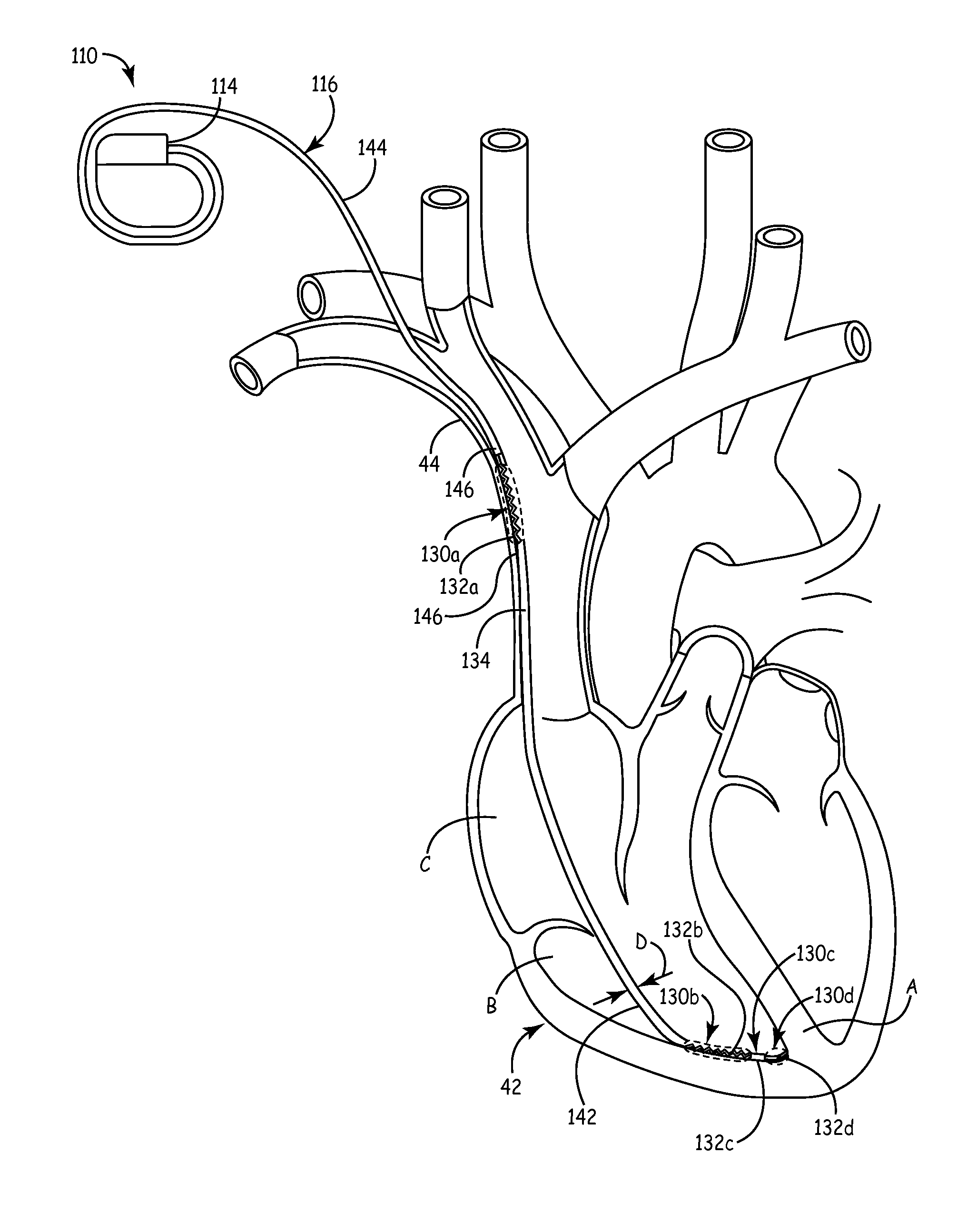
[0008]An implantable medical device is also provided. The implantable medical device can include a body assembly. The body assembly can transmit at least one electrical signal to treat an anatomical structure and can be adapted to receive at least one signal from the anatomical structure. The implantable medical device can include a cardiac lead in communication with the body assembly to enable communication between the body assembly and the anatomical structure. The cardiac lead including at least one multilumen member with a proximal portion, a distal portion, and a transition zone therebetween. The proximal portion can be coupled to the body assembly and the distal portion can be adapted to be coupled to the anatomical structure. The at least one multilumen member can also have a plurality of conduits. The implantable medical device can include a plurality of electrode assemblies, which can be coupled to the at least one multilumen member. Each of the plurality of electrode assemblies can have a transmission member in communication with the body assembly to communicate electrical signals. Each one of the plurality of transmission members can be received within a respective one of the plurality of conduits. The implantable medical device can also include a plurality of jumper members, with one of the plurality of jumper members disposed over one of the plurality of transmission members at the transition zone to enable the plurality of transmission members to transition from the proximal portion of the at least one multilumen member to the distal portion. Thus, the transition zone can optimize the performance of the conductors by allowing the implantable medical device to adapt to the surrounding anatomical structure.

Problems solved by technology

However, after disease or injury, certain tissues may no longer operate within general anatomical norms.
For example, after disease, injury, age, or combinations thereof, the heart muscle may begin to experience certain failures or deficiencies.

Method used


Image

  • System and method for cardiac lead
  • System and method for cardiac lead
  • System and method for cardiac lead

Examples


Embodiment Construction

[0047]Example embodiments will now be described more fully with reference to the accompanying drawings.

[0048]The following description may be merely exemplary in nature and is not intended to limit the present disclosure, application, or uses. It should be understood that throughout the drawings, corresponding reference numerals indicate like or corresponding parts and features. As indicated above, the present teachings are directed towards providing a system and method for relieving strain experienced by a cardiac lead system. It should be noted, however, that the present teachings could be applicable to any appropriate procedure in which it can be desirable to relieve strain in a multi-lumen structure. Therefore, it will be understood that the following discussions are not intended to limit the scope of the appended claims.

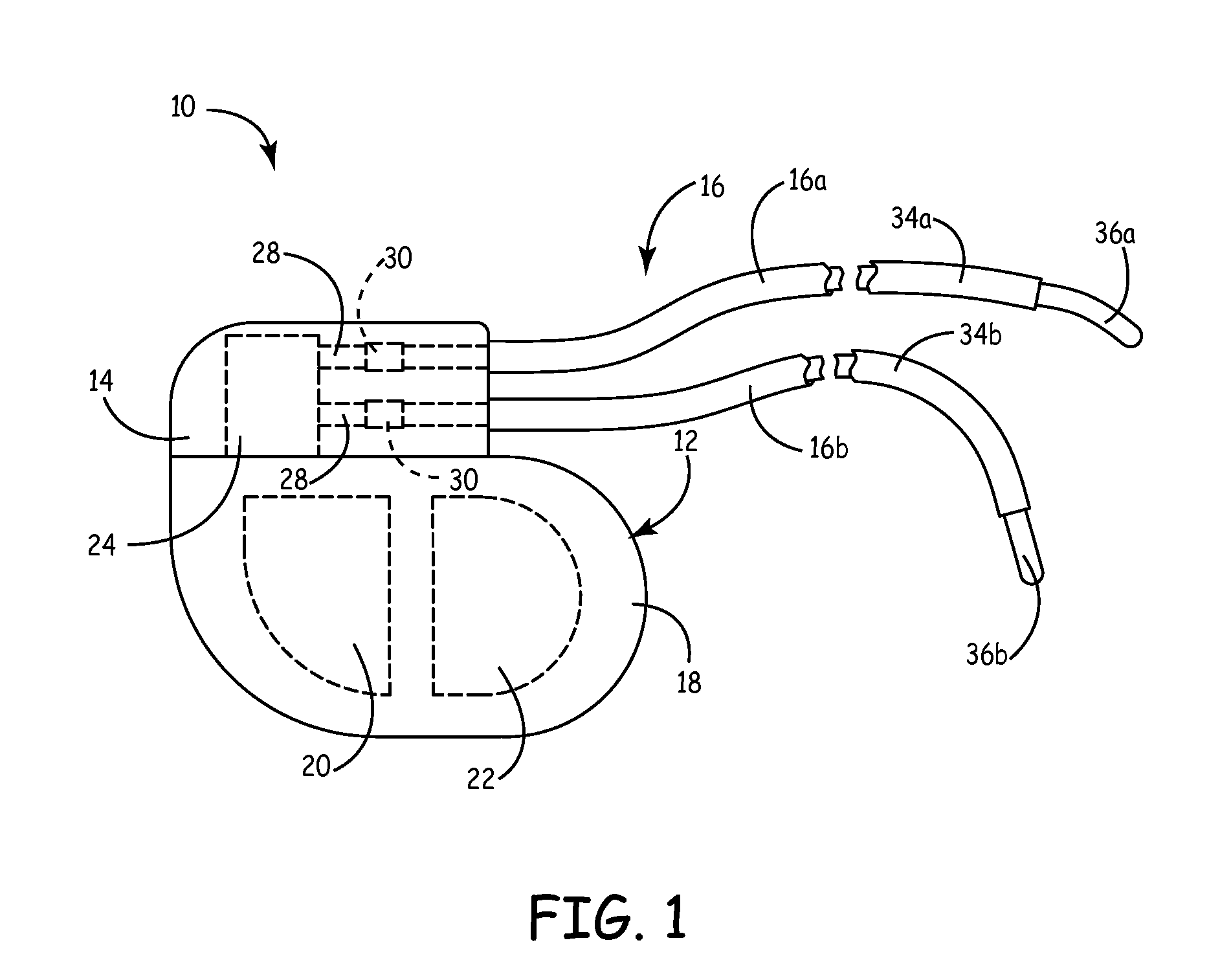
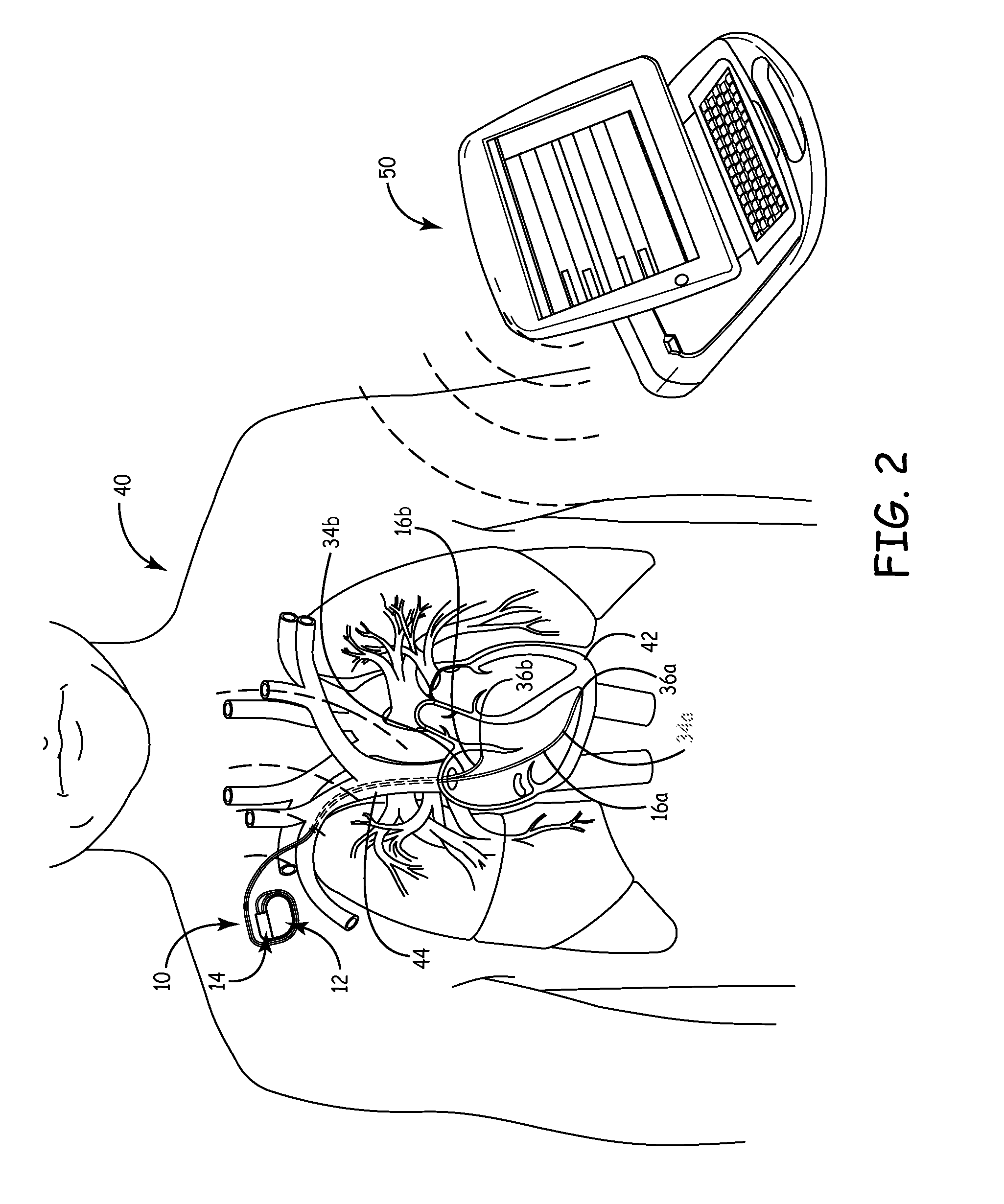
[0049]With reference to FIG. 1, an implantable medical device (IMD) 10, which can include implantable pulse generator (IPG) devices, implantable cardioverter-de...


PUM


Abstract

An implantable medical device (IMD) can include implantable pulse generator (IPG) devices, implantable cardioverter-defibrillators (ICD), cardiac resynchronization therapy defibrillator devices, neurostimulators or combinations thereof. In one example, the IMD can include a body assembly, which can provide at least one electrical signal corresponding to a therapy. The IMD can also include a cardiac lead assembly, which can have a proximal portion and a distal portion. The proximal portion of the cardiac lead assembly can be in communication with the body assembly to receive the therapy and the distal portion can be adapted to be coupled to an anatomical structure to transmit the at least one electrical signal to the anatomical structure. The proximal portion of the cardiac lead assembly can have a first stiffness and the distal portion can have a second stiffness. The first stiffness can be greater than the second stiffness.

Description

CROSS-REFERENCE TO RELATED APPLICATIONS[0001]This application claims the benefit of U.S. Provisional Application No. 61 / 142,292, filed on Jan. 2, 2009. The entire disclosure of the above application is incorporated herein by reference.INTRODUCTION[0002]This section provides background information related to the present disclosure which is not necessarily prior art.[0003]The human anatomy includes many types of tissue that can either voluntarily or involuntarily perform certain functions. For example, the cardiac or heart muscle involuntarily contracts to propel blood from atria and ventricles to blood vessels of the circulatory system. However, after disease or injury, certain tissues may no longer operate within general anatomical norms. For example, after disease, injury, age, or combinations thereof, the heart muscle may begin to experience certain failures or deficiencies. Some of these failures or deficiencies can be corrected or treated with implantable medical devices (IMDs)....

Claims


Application Information

Patent Timeline
Patent Type & Authority Applications(United States)
IPC IPC(8): A61N1/05
CPCA61M25/0032A61N1/056A61M25/04A61M25/0054A61M25/0013A61N1/0488A61N1/3956
Inventor OLSON, NATHAN LEE
Owner MEDTRONIC INC
Learn More