
Device and method for computer-assisted 2d navigation in a medical procedure

a technology of computer-aided 2d navigation and medical procedures, applied in the field of devices and methods for computer-aided 2d navigation, can solve the problem that important image information may possibly be covered, and achieve the effect of improving clinical workflow

Inactive Publication Date: 2011-01-06
SIEMENS AG
View PDF8 Cites 9 Cited by
  • Summary
  • Abstract
  • Description
  • Claims
  • Application Information

AI Technical Summary

Benefits of technology

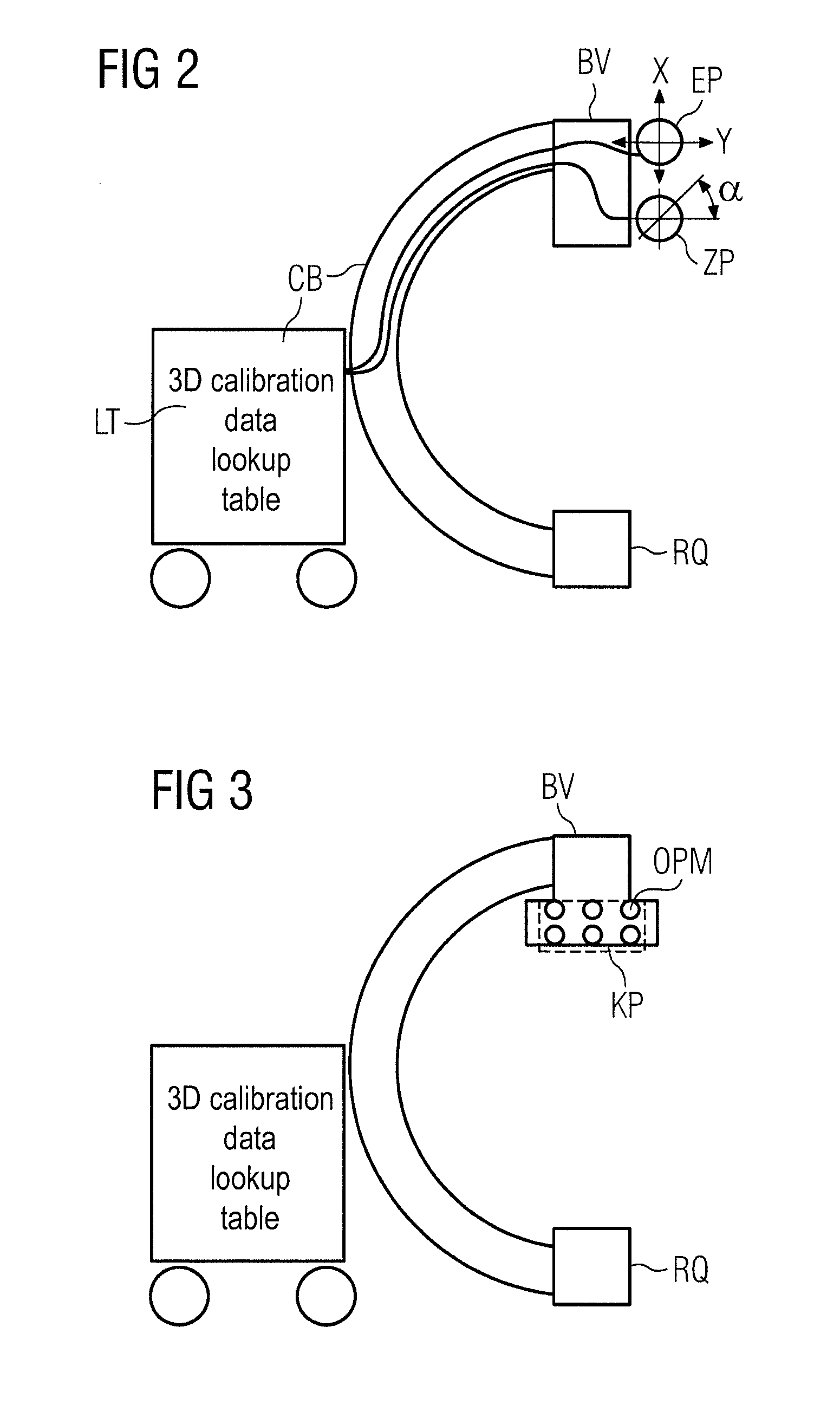
[0009]The subject matter of the invention has the advantage that the use of x-ray marker spheres arranged in at least two planes is not needed since respective projection matrices with extrinsic and intrinsic parameters can be determined from the 3D calibration data.
[0011]The invention also has the advantage that no information in the x-ray images is occluded by imaged x-ray markers.

Problems solved by technology

Previous methods for image registration entail the disadvantage that important image information may possibly be covered by the metal spheres of the x-ray markers that are imaged in the x-ray image.

Method used


Image

  • Device and method for computer-assisted 2d navigation in a medical procedure
  • Device and method for computer-assisted 2d navigation in a medical procedure
  • Device and method for computer-assisted 2d navigation in a medical procedure

Examples


Embodiment Construction

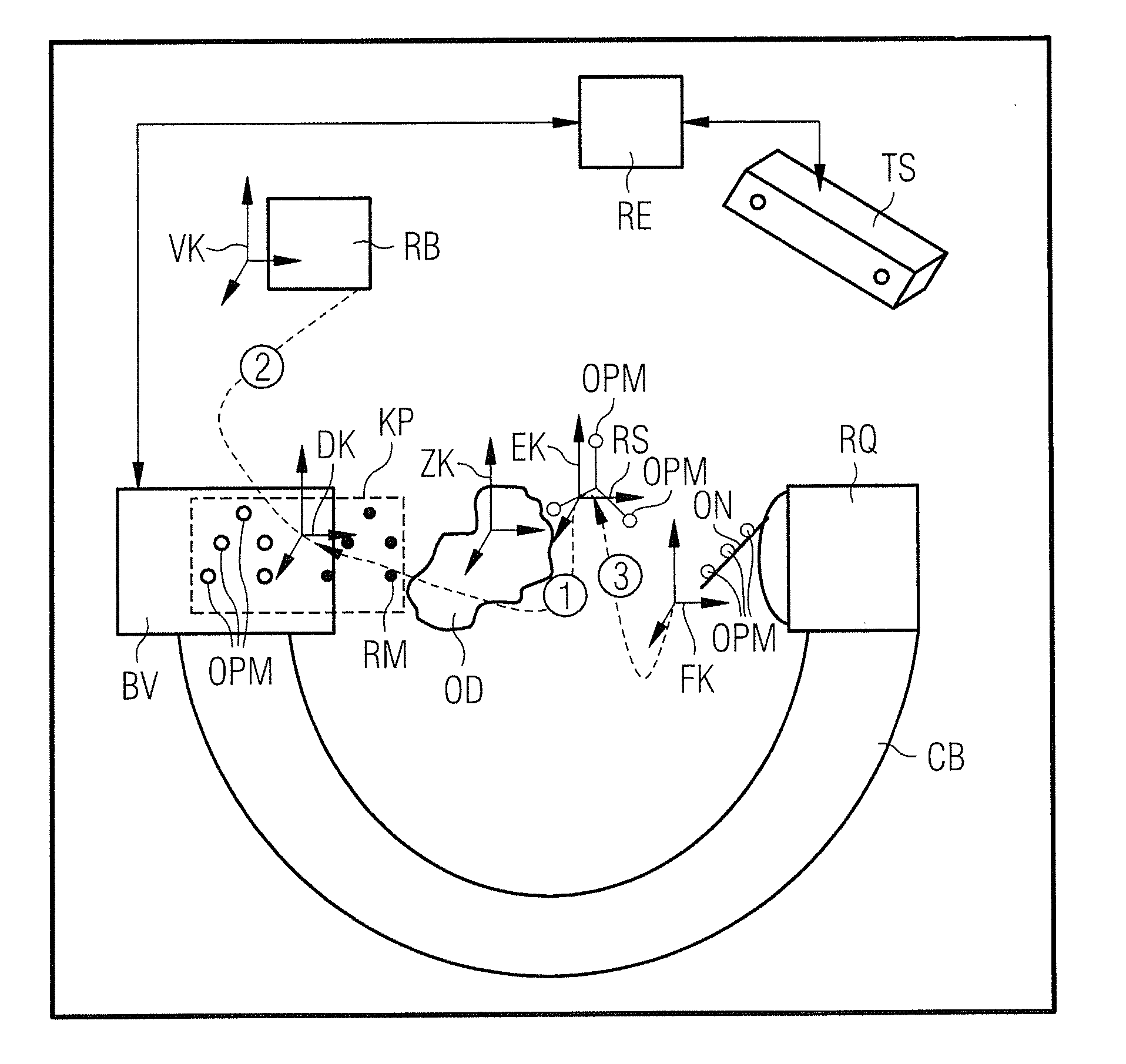
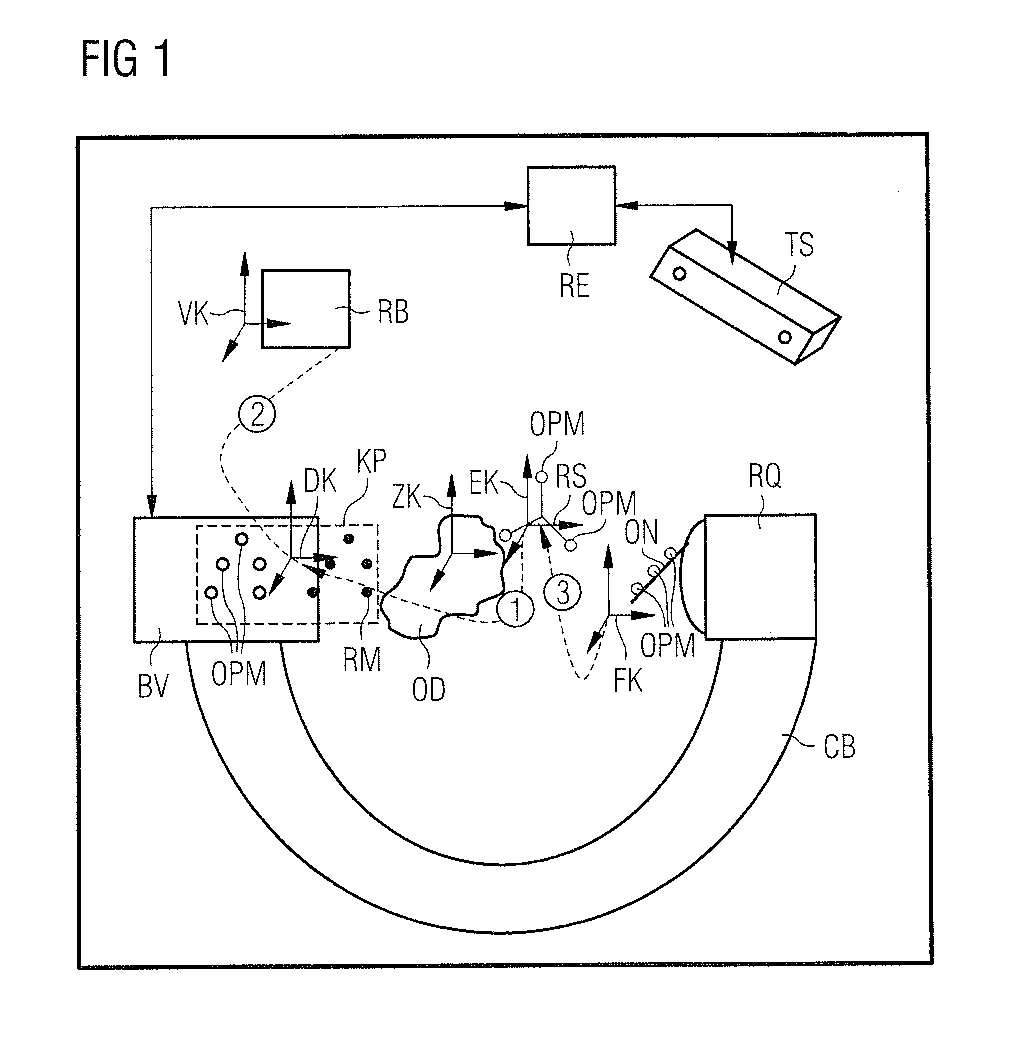
[0017]For a better understanding of the subject matter of the invention, a known type of registration is described. A tracking camera TS, a computer RE to link the collected image or x-ray image data, an x-ray unit CB (composed of x-ray source RQ and a detector or an image intensifier unit BV) are shown for the realization of the registration method. For example, the two-dimensional x-ray images that can be acquired at the detector BV of the x-ray unit CB can be merged into a volume image in the computer RE. For example, the optical information acquired by the cameras of the tracking unit TS—the optical information of the optical markers, for example—are evaluated in the same computer RE. Optical markers are arranged at a stationary hardware interface KP on the housing of the image intensifier BV of the C-arm CB, at a reference star RS which is mounted on an object OD and on a surgical instrument ON. For example, the optical markers are attached to a star with three arms. This star ...


PUM


Abstract

In a device and method for computer-assisted 2D navigation in a medical procedure, parameters of projection matrices of a 3D calibration process of a C-arm unit are used for the 2D navigation.

Description

BACKGROUND OF THE INVENTION[0001]1. Field of the Invention[0002]The subject matter of the invention is a device and a method for computer-assisted 2D navigation implemented during a medical procedure.[0003]2. Description of the Prior Art[0004]A number of steps, in particular coordinate transformations between various coordinate systems respectively associated with different objects, are needed for image registration in a medical procedure. In navigation during such a procedure, in particular in a computer-assisted navigation, the positions of trackable objects (for example instruments, patient clamps, marker rings) are detected at the x-ray image intensifier of a Fluoroscopy system. A characteristic arrangement of at least three optical markers is located on each trackable object. These three optical markers can be arranged, for example, in a star configuration. In previous known 2D navigation methods, the bearing of the x-ray image relative to the beam geometry is detected via x-ra...

Claims


Application Information

Patent Timeline
Patent Type & Authority Applications(United States)
IPC IPC(8): G06F19/00
CPCA61B6/4441A61B2019/5238A61B19/5244A61B6/547A61B34/20A61B2090/376
Inventor RINGHOLZ, MARTINSCHNEIDER, STEFAN
Owner SIEMENS AG
Learn More