

Tube alignment functionality for mobile radiography systems
a radiography system and mobile technology, applied in the field of imaging systems, can solve the problems of not living up to the expectations of image quality and/or radiation dosage of mobile imagers
- Summary
- Abstract
- Description
- Claims
- Application Information
AI Technical Summary
Benefits of technology
Problems solved by technology
Method used
Image

Examples
Embodiment Construction
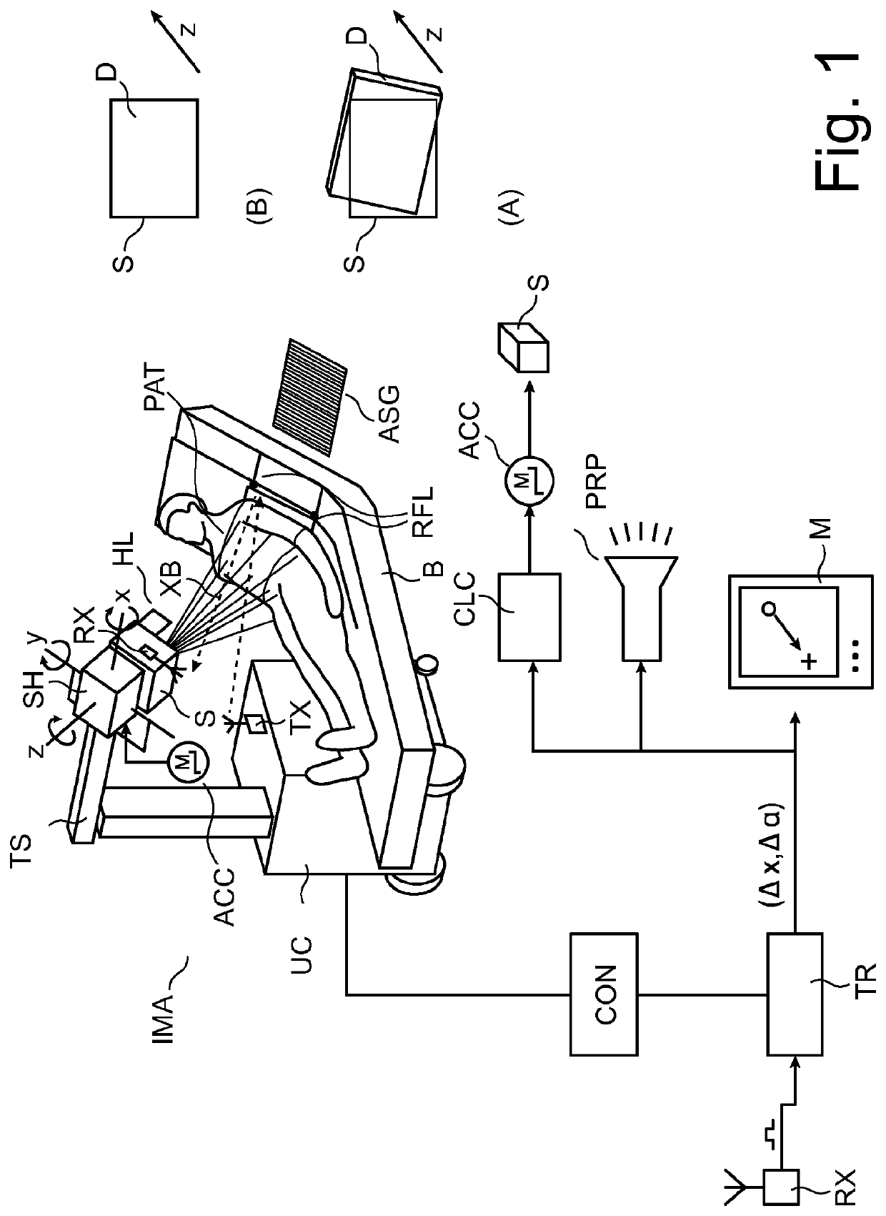
[0060]With reference to FIG. 1 there is shown an arrangement including a mobile X-ray imaging apparatus IMA. According to one embodiment, the apparatus is of the “dolly type” and comprises an undercarriage UC on rollers so as to be position-able at a convenient location relative to a patient PAT. The imager IMA is mobile in the sense that it is not permanently installed at a fixed place such as a room, but can be moved about from location to location as desired. One possible clinical application (as exemplary indicated in FIG. 1) is bedside chest X-ray but other uses are also envisaged for instance, in A&E, where X-ray images are frequently required of other body parts such as a patient's hand, foot, leg or head if an examination for injuries is called for.
[0061]There is an operator console CON built into the undercarriage for clinical personnel (in the following referred to as operator or user) to operate imager EMA. Console CON allows user to control image acquisition by releasing...
PUM
 Abstract
Description
Claims
Application Information