Pressure Measuring Device

Active Publication Date: 2011-01-13
ROBERT BOSCH GMBH +1
View PDF11 Cites 37 Cited by
  • Summary
  • Abstract
  • Description
  • Claims
  • Application Information

AI Technical Summary

Benefits of technology

[0004]The pressure measuring device according to the present invention has the advantage that the force path for measuring the pressure prevailing in th

Problems solved by technology

DE 103 43 521 has the disadvantage that when the pressure measuring glow plug is installed in

Method used


Image

  • Pressure Measuring Device
  • Pressure Measuring Device
  • Pressure Measuring Device

Examples


Embodiment Construction

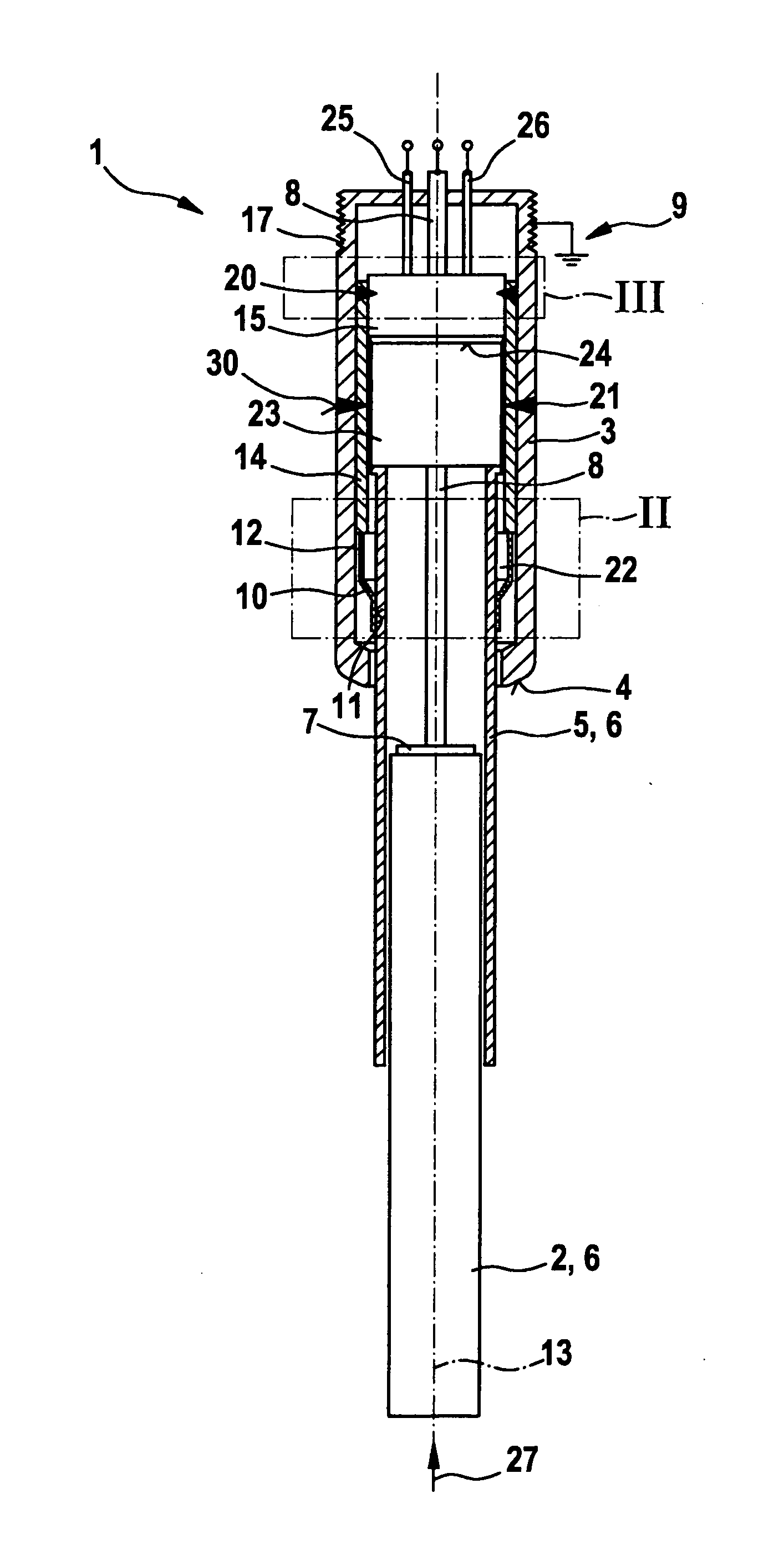
[0012]FIG. 1 shows a first exemplary embodiment of a pressure measuring device 1 in an axial sectional representation. Here, pressure measuring device 1 is fashioned as a pressure measuring glow plug 1 for an air-compressing, self-igniting internal combustion engine. In pre-chamber and turbulence chamber engines, a rod-shaped heating element 2 of pressure measuring glow plug 1 extends into the chamber of the internal combustion engine, and in engines having direct injection it extends into a combustion chamber of the engine. However, pressure measuring glow plug 1 according to the present invention is also suitable for other cases of application. In addition, pressure measuring device 1 can also be fashioned as a pressure measuring spark plug or pressure measuring injection valve for mixture-compressing, externally ignited internal combustion engines.

[0013]Pressure measuring glow plug 1 has a housing 3 on which a sealing cone 4 is fashioned. Rod-shaped heating element 2 is surrounde...


PUM


Abstract

A pressure measuring device suitable for disposition in a chamber of an internal combustion engine. The pressure measuring device has a housing, a force transmitting element that is effectively connected to a pressure sensor, and a sensor cage that surrounds the pressure sensor. The sensor cage is connected to the housing by a circumferential weld seam only at one connection segment of the housing. In this way, it is possible to achieve a defined pre-tensioning of a metal diaphragm that is connected on the one hand to the sensor cage and on the other hand to the force transmitting element.

Description

FIELD OF THE INVENTION[0001]The present invention relates to a pressure measuring device for disposition in a chamber of an internal combustion engine. Specifically, the present invention relates to a pressure measuring glow plug for disposition in a pre-chamber, turbulence chamber, or combustion chamber of an air-compressing self-igniting internal combustion engine.BACKGROUND INFORMATION[0002]German Patent Application No. DE 103 43 521 describes a pressure measuring glow plug for a diesel engine. The known pressure measuring glow plug has a plug body that is to be placed into a cylinder of the diesel engine. Moreover, the known pressure measuring glow plug has a heating rod situated in the plug body and a pressure sensor that is situated between the heating rod and the plug body. The pressure sensor is influenced by the pressure transmitted by the heating rod in the combustion chamber of the cylinder. Moreover, the known pressure measuring glow plug has a diaphragm that is connecte...

Claims


Application Information

Patent Timeline
IPC IPC(8): G01M15/08
CPCF02P19/028F23Q2007/002G01L23/10F23Q7/001
Inventor KERN, CHRISTOPHHESS, REINHOLDZACH, REIKOKLEINDL, MICHAELWOLFER, PETERSCHOTT, STEFFENCAVALLONI, CLAUDIOSALTIKOV, PAVLOMUELLER, MICHAELBERTOLA, ANDREA
Owner ROBERT BOSCH GMBH
Why Eureka
Try Eureka