
Intercooling control system and method of diesel engine

A control system and control method technology, applied in engine control, electrical control, fuel injection control, etc., can solve problems such as inaccurate intake air flow measurement, and achieve the effect of improving measurement accuracy

Active Publication Date: 2018-04-20
WEICHAI POWER CO LTD
View PDF5 Cites 2 Cited by
  • Summary
  • Abstract
  • Description
  • Claims
  • Application Information

AI Technical Summary

Problems solved by technology

[0005] The purpose of the present invention is to provide a diesel engine intercooling control system and control method to solve the technical problem of inaccurate intake air flow measurement in the prior art

Method used


Image

  • Intercooling control system and method of diesel engine
  • Intercooling control system and method of diesel engine
  • Intercooling control system and method of diesel engine

Examples


Embodiment 1

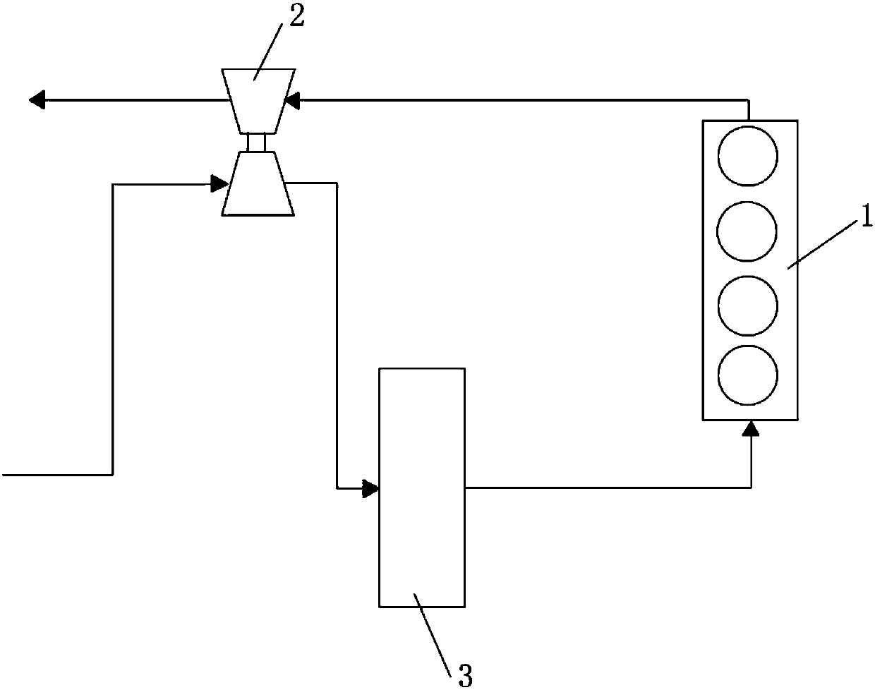
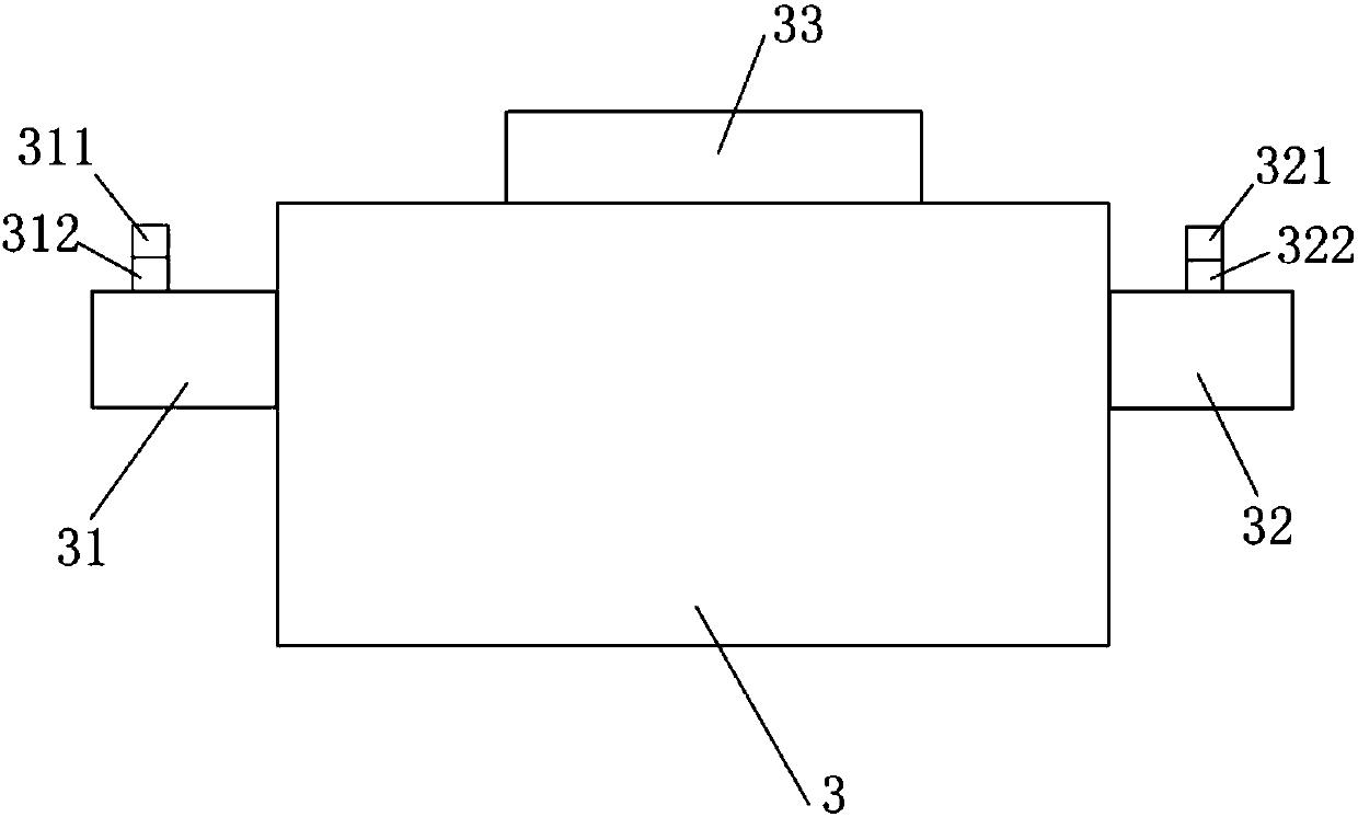
[0041] Such as figure 1 and figure 2 As shown, the present embodiment provides an intercooling control system for a diesel engine, including an engine 1, a turbocharger 2 and an intercooler 3, the exhaust channel of the engine 1 is connected with the exhaust gas inlet of the turbocharger 2, and the turbocharger The air outlet of the compressor 2 is connected to the air inlet of the intercooler 3, and the air outlet of the intercooler 3 is connected to the intake passage of the engine 1; the intercooler 3 is integrated with a front straight pipe section 31 and / or a rear straight pipe section 32 , the front straight pipe section 31 is provided with a first pressure sensor 311 and a first temperature sensor 312, or the rear straight pipe section 32 is provided with a second pressure sensor 321 and a second temperature sensor 322, and the intercooler 3 is also integrated with data processing Unit 33, the data processing unit 33 has the functions of data acquisition, data process...

Embodiment 2

[0053]This embodiment provides an intercooler control system for a diesel engine. For simplicity, only the differences from Embodiment 1 will be described. The difference is that, in this embodiment, the front straight pipe section 31 is provided with a first pressure sensor 311 and a first temperature sensor 312 , and the rear straight pipe section 32 is provided with a second pressure sensor 321 and a second temperature sensor 322 .

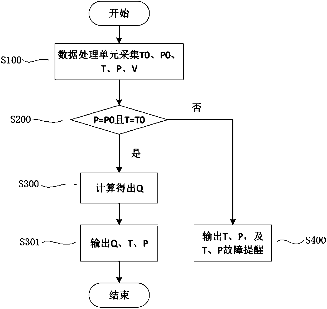
[0054] Such as Figure 4 As shown, the control method of the intercooling control system of the diesel engine provided in this embodiment is as follows:

[0055] It should be noted in advance that steps S100 and S200 occur when the engine is not started, and steps S300, S301, S400, S401, S501 and S600 occur after the engine is started.

[0056] S100, the data processing unit 33 collects the temperature value T1 of the first temperature sensor 312, the pressure value P1 of the first pressure sensor 311, the temperature value T2 of the second te...


PUM


Abstract

The invention relates to an intercooling control system and method of a diesel engine. The intercooling control system comprises the engine, a turbocharger, an intercooler and a data processing unit.A front straight pipe section and / or a rear straight pipe section are integrated into the intercooler, and a temperature sensor and a pressure sensor are arranged on each of the front straight pipesection and / or the rear straight pipe section. According to the intercooling control system and method, the adopted temperature sensors and the pressure sensors are arranged on the front straight pipe section and / or the rear straight pipe section of the intercooler, a measuring point is located at a round straight pipe, compared with a measuring point position of an air intake manifold, pressure measuring can be better conducted, and the measurement accuracy of the air intake flow rate is improved; and in addition, the data processing unit is further integrated into the intercooler, the data processing unit has the functions of data collecting, data processing and data outputting so that air intake parameters can be actively output by the intercooling control system, and pitch points in need can use the air intake parameters.

Description

technical field [0001] The invention relates to the technical field of diesel engines, in particular to an intercooling control system and control method for diesel engines. Background technique [0002] When the electronically controlled diesel engine is working, it will first calculate the basic fuel injection quantity under the ideal state according to the information such as vehicle speed and accelerator pedal position, and then calculate the basic fuel injection quantity according to the intake air temperature, intake flow rate, coolant temperature, engine status, oxygen sensor signal, etc. information to calculate the final injection quantity. [0003] In the prior art, there are usually two ways to obtain the intake air flow: the first is to install a hot wire and a hot-film intake air flow meter in front of the fresh air intake of the turbocharger, and directly measure the intake air flow through the intake air flow meter. The second is to install a pressure sensor ...

Claims


Application Information

Patent Timeline
IPC IPC(8): F02B29/04F02D41/18
CPCF02B29/04F02D41/18Y02T10/12
Inventor 黄鑫章棵张露捷杜志良黎程宋军李乐生周宇
Owner WEICHAI POWER CO LTD
Learn More