Cap transfer unit having a movable cap pusher

a transfer unit and pusher technology, applied in the field of container caps, can solve the problems of air nozzles, cap damage, major difficulty, etc., and achieve the effect of reducing the risk of cap damage and enhancing reliability

Active Publication Date: 2011-01-13
SIDEL PARTICIPATIONS SAS
View PDF19 Cites 2 Cited by
  • Summary
  • Abstract
  • Description
  • Claims
  • Application Information

AI Technical Summary

Benefits of technology

[0009]It is an object of the invention to provide a cap transfer unit with enhanced reliability, reducing the risk of cap damage.

Problems solved by technology

Furthermore, since the environment in the sterilization chamber must be kept sterile, it is not allowed to use air nozzles to force the caps along the transfer line.
Such a design may lead to a major difficulty.
When caps are missing upstream the transfer wheel, e.g. because of an upstream cap jam or emptiness of the hopper, the caps standing along the transfer path in the sterilization chamber are stopped, thereby leading to cap damage.

Method used


Image

  • Cap transfer unit having a movable cap pusher
  • Cap transfer unit having a movable cap pusher
  • Cap transfer unit having a movable cap pusher

Examples


Embodiment Construction

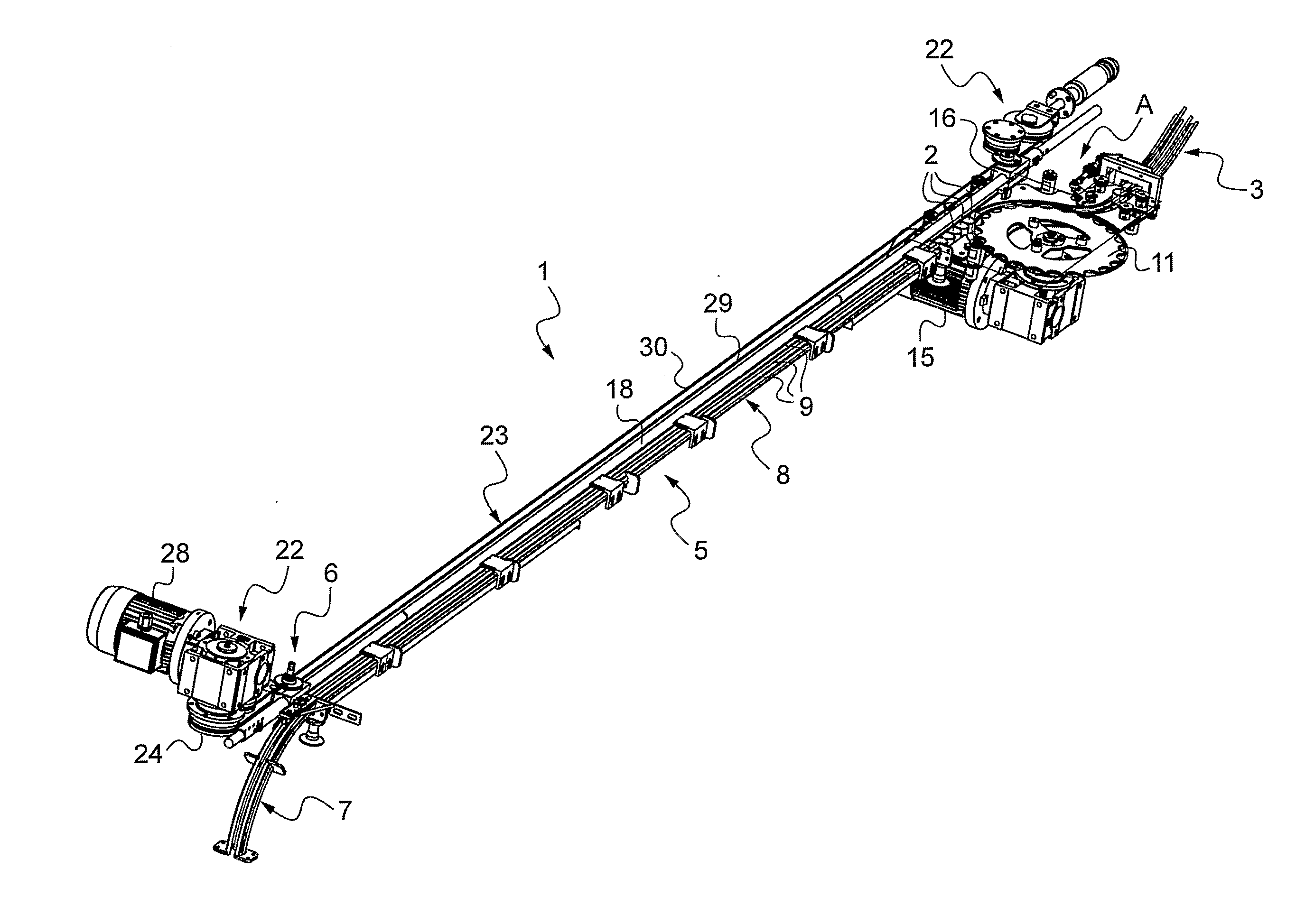
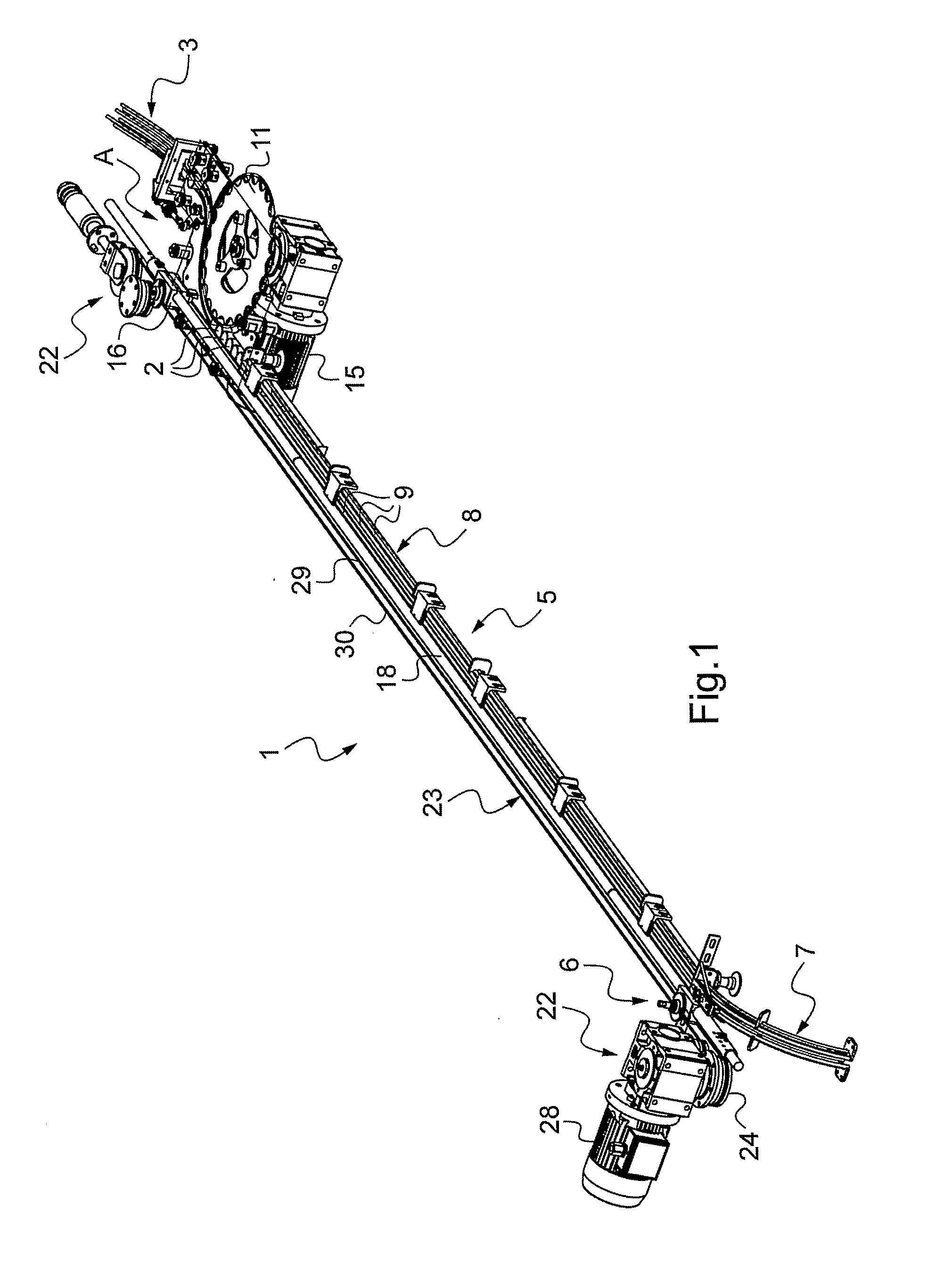
[0017]Turning now to the drawings, there is shown a cap transfer unit 1, as part of a container handling machine in which containers are sterilized, filled and then capped.

[0018]Caps 2 are put in bulk in a hopper (not shown), for example of the rotating / vibrating type, standing on top of a machine frame, and fed from the hopper to an upstream cap feeding line 3 receiving a row of caps 2.

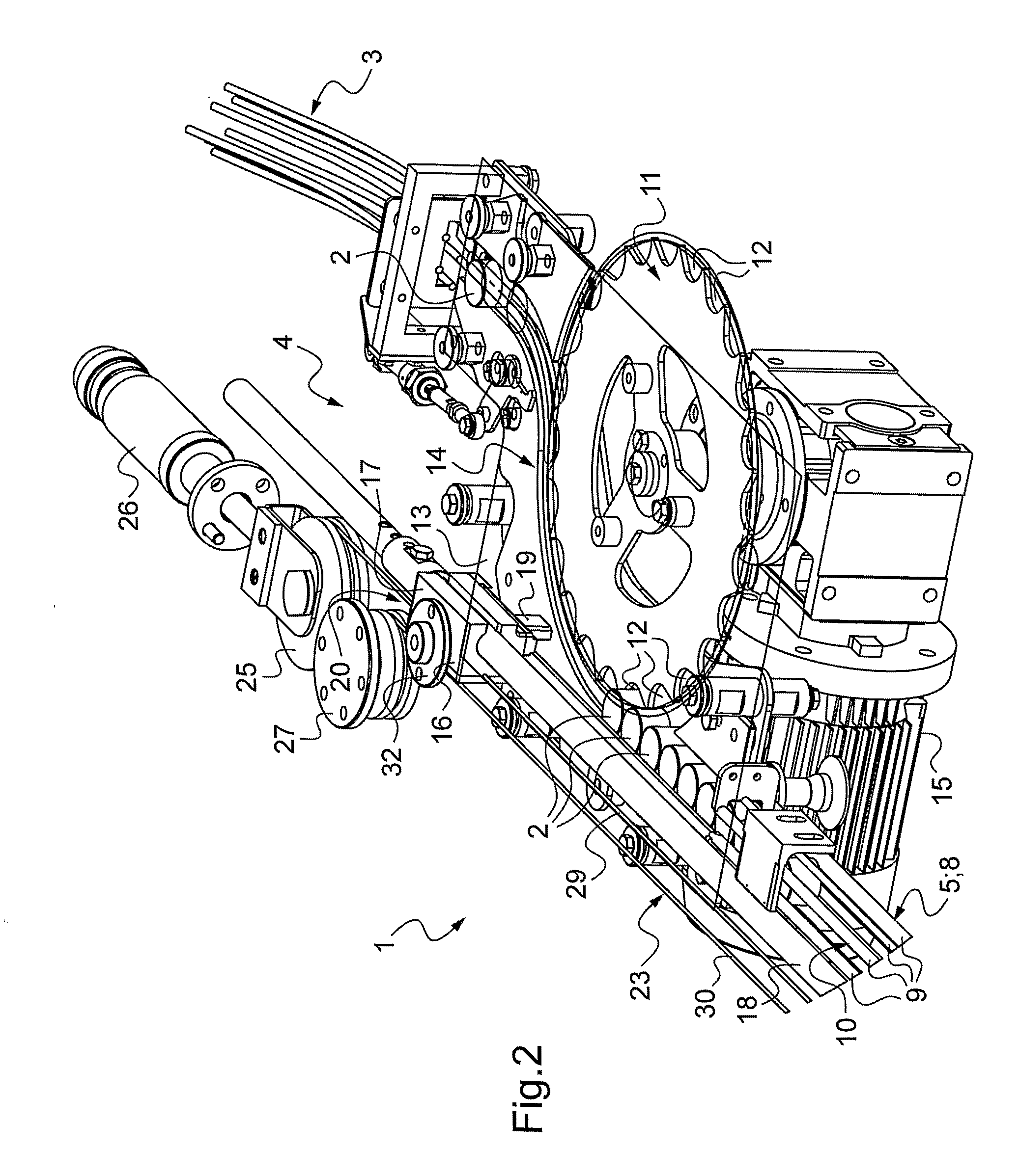
[0019]The cap feeding line 3 moves the caps 2 from the hopper to a loading area 4 where caps 2 are fed to the cap transfer unit 1. Caps 2 are then transferred by the cap transfer unit 1, with their concavity oriented downwards, from the cap loading area 4, along a cap transfer path 5, to a cap discharge area 6. In the cap discharge area 6, caps 2 are fed to a downstream cap feeding line 7 in which caps are moved to a container capping unit, where caps 2 are put on the mouths of the containers and screwed thereto.

[0020]The cap transfer path 5 goes horizontally in straight line across a cap sterilizati...


PUM


Abstract

A cap transfer unit (1) comprising a cap transfer line (8) defining a transfer path (5) from a cap loading area (4) to a cap discharge area (6), and a cap pusher (16) slidingly mounted along the cap transfer line (8), the cap pusher (16) having a rest position in which the cap pusher (16) is spaced from the transfer path (5), and an active position in which the cap pusher (16) overlaps at least partially the transfer path (5) for coming into abutment with caps (2) located therein.

Description

FIELD OF THE INVENTION[0001]The invention relates to the container industry, and more specifically to the capping of containers.BACKGROUND OF THE INVENTION[0002]Once filled, containers are immediately capped, at a capping unit, with caps supplied by a cap feeding unit.[0003]In an ordinary cap feeding unit, caps are supplied from a hopper into a cap feeding line where caps are moved in at least one row towards the capping unit. As caps are initially stored in a non-sterile environment (such as a hopper), they are generally sterilized before they reach the capping unit.[0004]More precisely, caps are generally moved by a cap transfer unit, along a transfer path, through a sterile chamber where sterilization is realized, e.g. by spraying hot hydrogen peroxide, in order to subsequently close the containers which have been filled in aseptic conditions. One may refer to US patent application No. US 2007 / 0006550 (SIG TECHNOLOGY) for further details regarding cap sterilization.[0005]Several ...

Claims


Application Information

Patent Timeline
Patent Type & Authority Applications(United States)
IPC IPC(8): B65G37/00B65G47/84B65G47/82
CPCB65B7/2807B67B3/003B65G47/82
Inventor CECI, IVANO
Owner SIDEL PARTICIPATIONS SAS
Why Eureka
Try Eureka