Jumping toy top

Inactive Publication Date: 2011-01-13
TOMY CO LTD
View PDF44 Cites 22 Cited by
  • Summary
  • Abstract
  • Description
  • Claims
  • Application Information

AI Technical Summary

Benefits of technology

According to an embodiment of the present invention, the contact portion can easily be formed with a simple structure by cutting the distal end of the spinning shaft obliquely.
According to an embo

Problems solved by technology

Since the above-described toy top jumps on contact with the opponent toy top to attack the opponent toy to

Method used


Image

  • Jumping toy top
  • Jumping toy top
  • Jumping toy top

Examples


Example

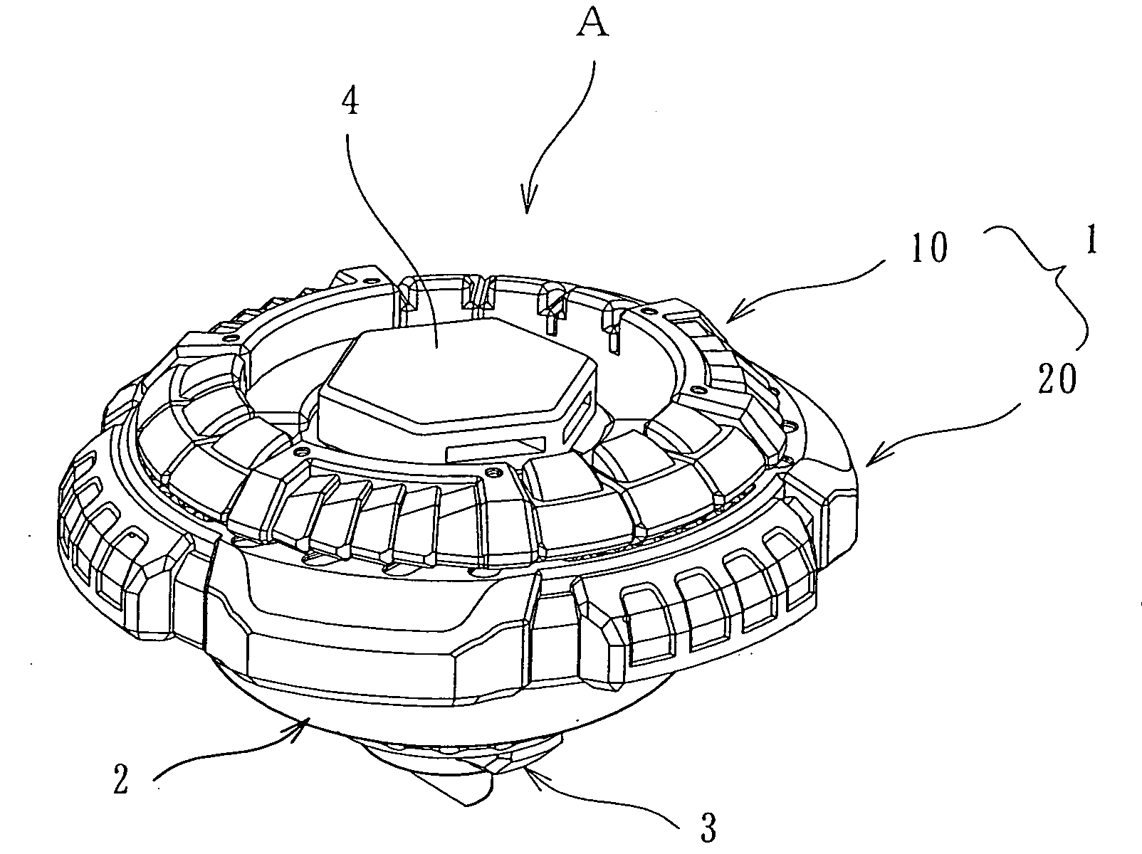
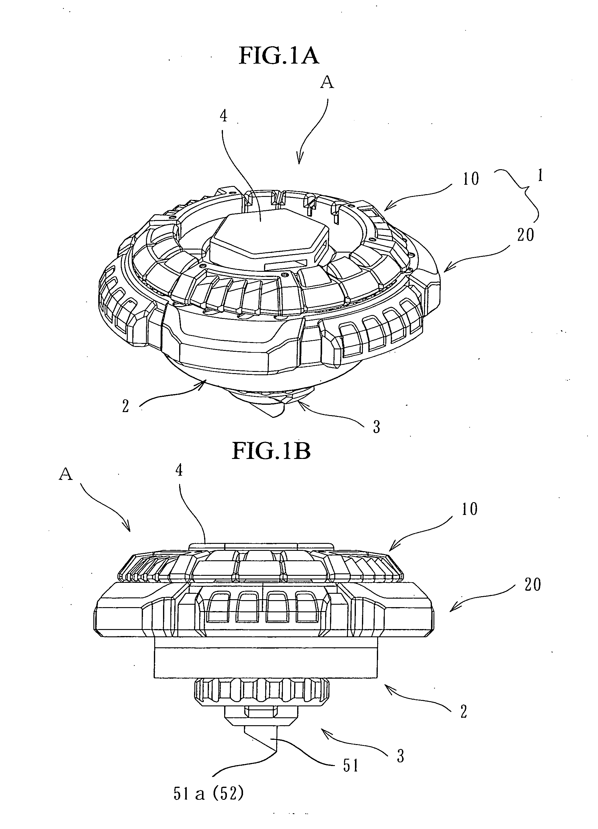
FIGS. 1A and 1B show an embodiment of a jumping toy top according to the present invention. A jumping toy top A includes a toy main body 1 which includes a first attacking member 10 and a second attacking member 20 and which is provided with a function of attacking an opponent toy top, a spinning shaft body 3, a shaft body supporting portion 2 for supporting the spinning shaft body 3, and a screw-like joining member 4 for joining the toy main body 1 and the shaft body supporting portion 2 to each other.

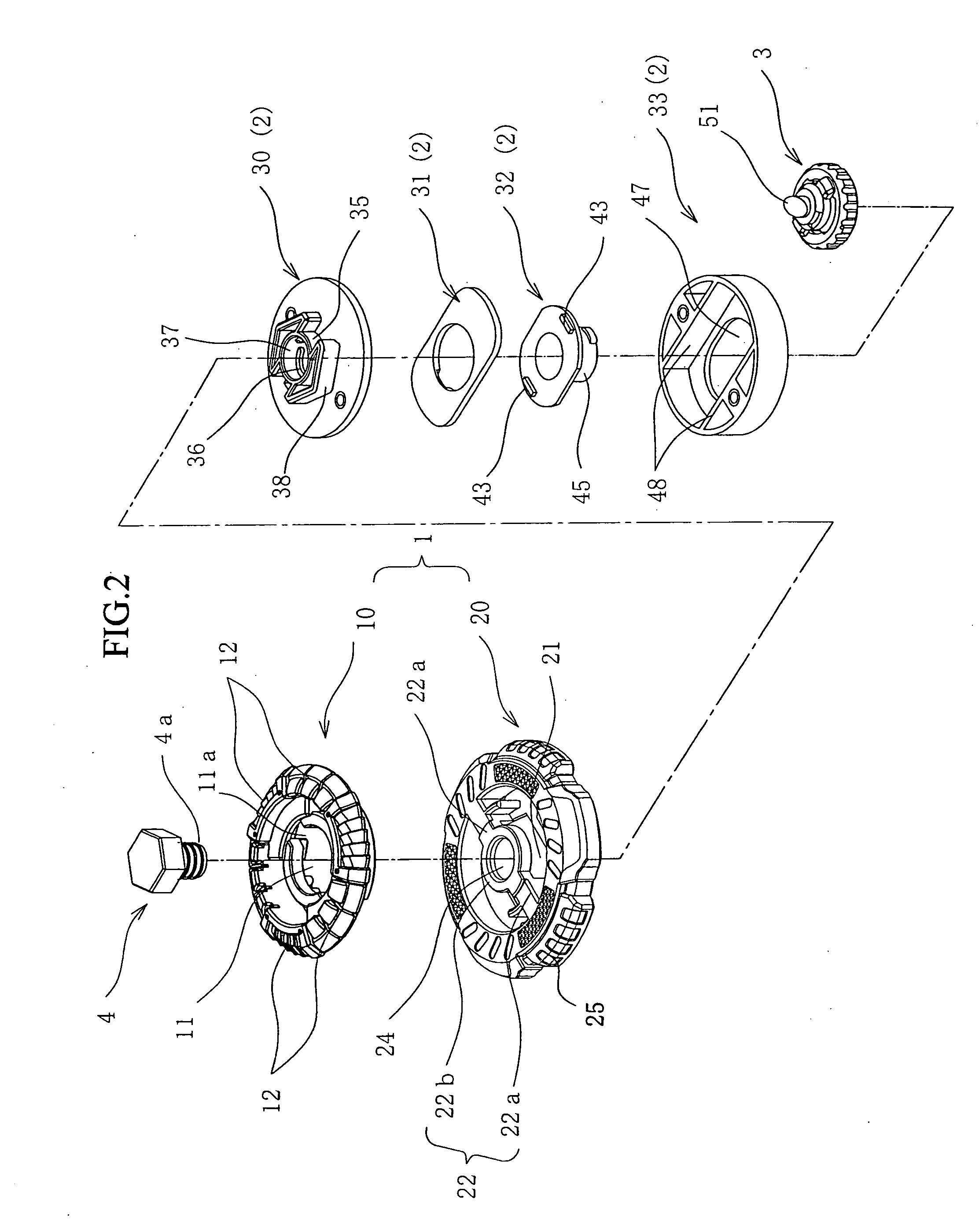
As shown in FIG. 2, the first attacking member 10 is a disk-like member made of synthetic resin and having a fitting hole portion 11 formed in the center thereof in which a fitting portion 22 of the second attacking member 20 described later is fitted. On diametrically opposite sides of the fitting hole portion 11 is formed a pair of engagement recesses 11a for engaging a bridge 22a to perform positioning when the fitting hole portion 11 is fitted on the fitting portion 22 of the seco...


PUM


Abstract

A toy top that can repeatedly jump on a curved playing surface to attack an opponent toy top from above. The jumping toy top includes a toy main body, a spinning shaft body having a spinning shaft, and a shaft body supporting portion disposed on the toy main body to support the spinning shaft body. A distal end of the spinning shaft has one side projecting downward more than another diametrically opposite side to configure a portion to contact a playing surface of a playing board. When the jumping toy top spins on a central axis of the toy main body, the contact portion revolves around the central axis of the toy main body in a circular orbit.

Description

CROSS REFERENCE TO RELATED APPLICATIONThe application claims the benefit under 35 U.S.C. Section 119 of Japanese Patent Application No. 2009-4809, filed Jul. 10, 2009, which is hereby incorporated by reference.BACKGROUND OF THE INVENTION1. Field of the InventionThe present invention relates to a jumping toy top, and in particular to a jumping toy top that jumps repeatedly on a playing board.2. Description of the Related ArtPreviously, a toy top that jumps on contact with an opponent toy top on a playing board has been proposed by the assignee of the present application (for example, Japanese Utility Model Registration No. 3079301). This toy top includes a jumping mechanism for making the toy top jump upward and an actuation piece protruding outward on an outer surface of a main body of the toy top, in which the jumping mechanism is actuated by the contact of the actuation piece with the opponent toy top.SUMMARY OF THE INVENTIONSince the above-described toy top jumps on contact with ...

Claims


Application Information

Patent Timeline
IPC IPC(8): A63F3/00A63H1/06
CPCA63H1/16
Inventor UJITA, HARUHISAMAEDA, TAKEAKI
Owner TOMY CO LTD
Why Eureka
Try Eureka