
Battery charging method and apparatus

Active Publication Date: 2011-01-13
SCHNEIDER ELECTRIC IT CORP
View PDF99 Cites 33 Cited by
  • Summary
  • Abstract
  • Description
  • Claims
  • Application Information

AI Technical Summary

Benefits of technology

[0007]Conventional charge profiles often require that the power supply used to charge the battery remain uninterrupted for a complete charge cycle in order to optimally charge the battery. In UPS and other applications, power outage timing can often not be predicted and the charging cycle can therefore be randomly interrupted and restarted. As a result, conventional approaches to battery charging may result in various problems with the battery. For example, intermittent charging may result in progressively reducing back-up time due to increased internal resistance of the battery caused by interruption of the charging power before sufficient de-sulphation of the electrodes has occurred, or drying up of the battery electrolyte due to over-charging, which can cause premature failure of the battery. Accordingly, aspects and embodiments disclosed herein are directed to improved systems and methods for charging batteries that address or mitigate these problems.

Problems solved by technology

In UPS and other applications, power outage timing can often not be predicted and the charging cycle can therefore be randomly interrupted and restarted.
As a result, conventional approaches to battery charging may result in various problems with the battery.
For example, intermittent charging may result in progressively reducing back-up time due to increased internal resistance of the battery caused by interruption of the charging power before sufficient de-sulphation of the electrodes has occurred, or drying up of the battery electrolyte due to over-charging, which can cause premature failure of the battery.
Applying the substantially constant voltage of the second value across the terminals of the battery may include applying a voltage with the second value being in a range sufficient to prevent self-discharge of the battery and insufficient to induce evaporation of electrolyte in the battery.

Method used


Image

  • Battery charging method and apparatus
  • Battery charging method and apparatus
  • Battery charging method and apparatus

Examples


example 1

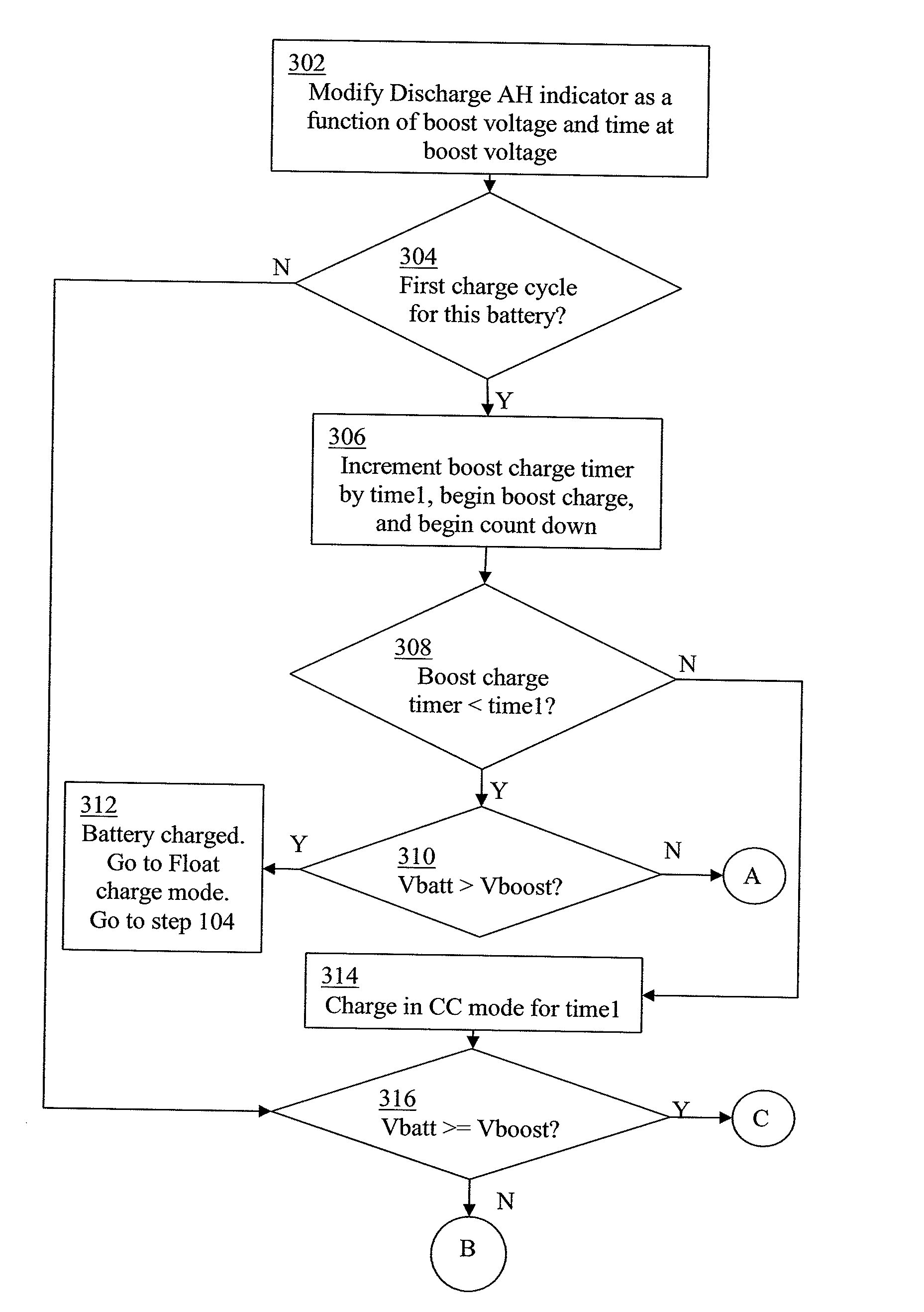
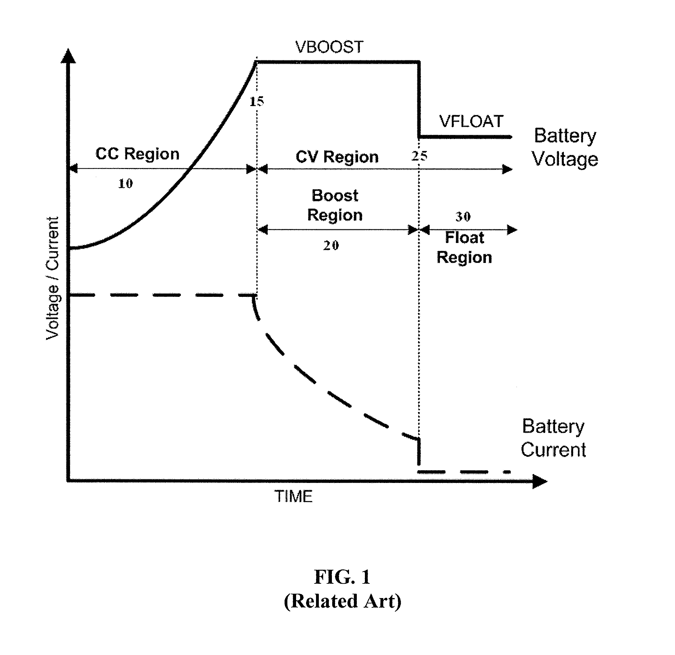
[0081]Referring to FIG. 12, there is illustrated a recorded charge profile for a battery when charged according to an embodiment of the present invention. The battery used was a lead-acid flat plate battery. As can be seen from FIG. 12, the battery was charged in constant current mode in region 10 until the battery voltage reached the boost region voltage level chosen for this battery, which in this instance was approximately 14.2 volts. The battery voltage reached this level at time 15, after just under 10 hours of charging in constant current mode. It should be noted that the charger was not able to provide truly constant current to the battery throughout the entirety of the constant current charge mode. The current supplied dropped from just over seven amps to just over six amps over the course of the constant current mode charging.

[0082]The boost region charging in region 20 was carried out for just over five hours. This was the amount of time calculated to replace the amount of...

example 2

[0085]A test was performed comparing the manufacturer's recommended charging profile to a charging method according to an embodiment of the present invention. The test was conducted using an APC model HI800SQ UPS system, which included Prestolite model PM12000 12V-120AH batteries. It was found that using the charging method according to an embodiment of the present invention the battery back-up capacity may be significantly retained over a number of charge cycles as opposed to the manufacturer's recommended charge method. As can be seen in Table 1 below, using the manufacturer's charging method (the “Old Algorithm”) the amount of back-up time available from the battery dropped from 91 minutes to 71 minutes over five discharge / charge cycles. In comparison, using a method according to an embodiment of the present invention (the “New Algorithm”), there was a significantly decreased drop in available back-up time over the same number of charge cycles—a drop of from about 88 minutes to 8...


PUM


Abstract

Disclosed are methods for charging batteries utilizing a charge balance approach, and charger systems using those methods. In one example, a method for charging a battery includes monitoring an amount of charge released by the battery while in a discharge state, recording the amount of charge released while in the discharge state, applying a voltage which results in current in reverse direction to the battery at a first voltage level for a time sufficient to introduce an amount of charge substantially equal to the recorded amount of charge released by the battery while in the discharge state, and maintaining the battery in a stand-by mode by applying a voltage which results in current in reverse direction to the battery at a second voltage level, the second voltage level being in a range sufficient to prevent self-discharge of the battery and insufficient to induce evaporation of electrolyte in the battery.

Description

BACKGROUND OF INVENTION[0001]1. Field of Invention[0002]The present invention is in the field of battery technology and, more specifically, relates to charging profiles for batteries used in inverter applications such as in conjunction with uninterruptable power supply (UPS) systems, or other applications that involve sporadic charging of batteries.[0003]2. Discussion of Related Art[0004]The use of uninterruptible power supplies to provide regulated, uninterrupted power for sensitive and / or critical loads, such as computer systems and other data processing systems, is known. A number of different UPS products are available including those identified under the trade name Smart-UPS® from American Power Conversion Corporation (APC) of West Kingston, R.I. In a typical UPS, a battery is used to provide backup power for a critical load during blackout or brownout conditions. Some examples of UPS systems include flooded cell lead-acid batteries that are used to provide back-up power. It ha...

Claims


Application Information

Patent Timeline
IPC IPC(8): H02J7/00
CPCH02J7/0078H02J7/048H02J7/044H02J7/009H02J7/00719H02J7/00716H02J7/04
Inventor SALIGRAM, NARAYANA PRAKASHNAIR, SREEJAKUMAR SREEKANTANKRISHNAN, RAMAKRISHNAN MADENOORDIGHRASKER, MILIND
Owner SCHNEIDER ELECTRIC IT CORP
Learn More