Vertical geophone having improved distortion characteristics

a geophone and distortion technology, applied in the field of geophones, can solve the problems of harmonic distortion and non-linear geophone response, greater parasitic flux leakage, lower parasitic reluctance, etc., and achieve the effect of simplifying frequency spring tuning and minimizing geophone distortion

Active Publication Date: 2011-01-13
GEOSPACE TECH
View PDF53 Cites 22 Cited by
  • Summary
  • Abstract
  • Description
  • Claims
  • Application Information

AI Technical Summary

Benefits of technology

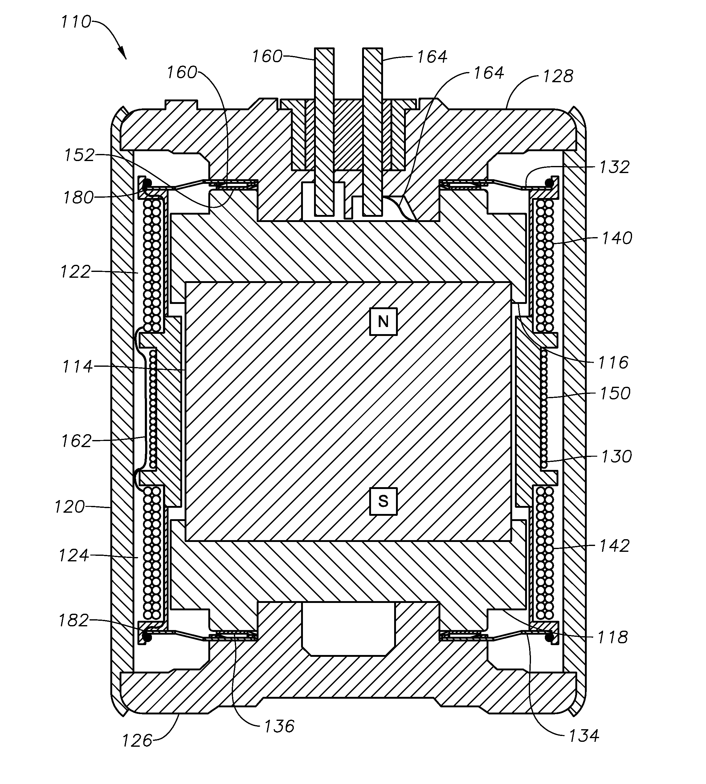
[0028]The geophone according to an embodiment of the invention is a vertical geophone that includes a lower frequency spring which is positioned directly on the lower end cap. This arrangement eliminates the “spring supported by a spring” arrangement of prior art geophones to minimize geophone distortion and simplify tuning of the frequency springs. A contact spring is positioned between the lower frequency spring and the lower pole piece for forming part of the geophone electrical circuit. One surface of the contact spring includes a plurality of wiper surfaces that ensure consistent sliding electrical contact against either the bottom surface of the lower pole piece or the upper surface of the lower frequency spring. The obverse surface of the contact spring is preferably spot welded to the upper surface of the lower frequency spring or the bottom surface of the lower pole piece, respectively.

Problems solved by technology

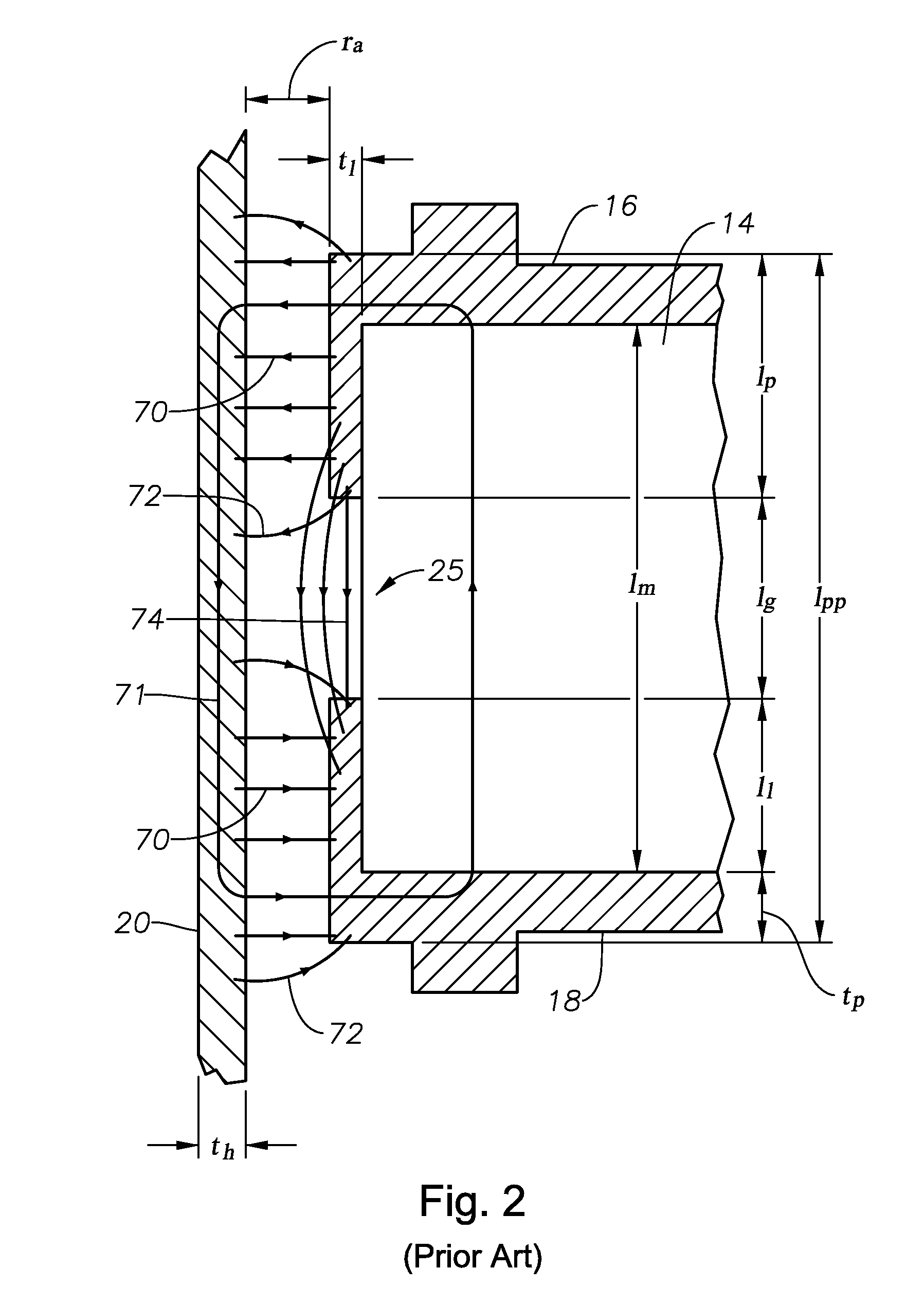
This fringing effect creates non-linearities in the magnetic flux density within the air gap, which results harmonic distortion and a non-linear geophone response.
This smaller lg results in lower parasitic reluctance, greater parasitic flux leakage, and thus a concomitant reduction in geophone sensitivity.
The result of these factors is an inability to tightly control the damping tolerance.
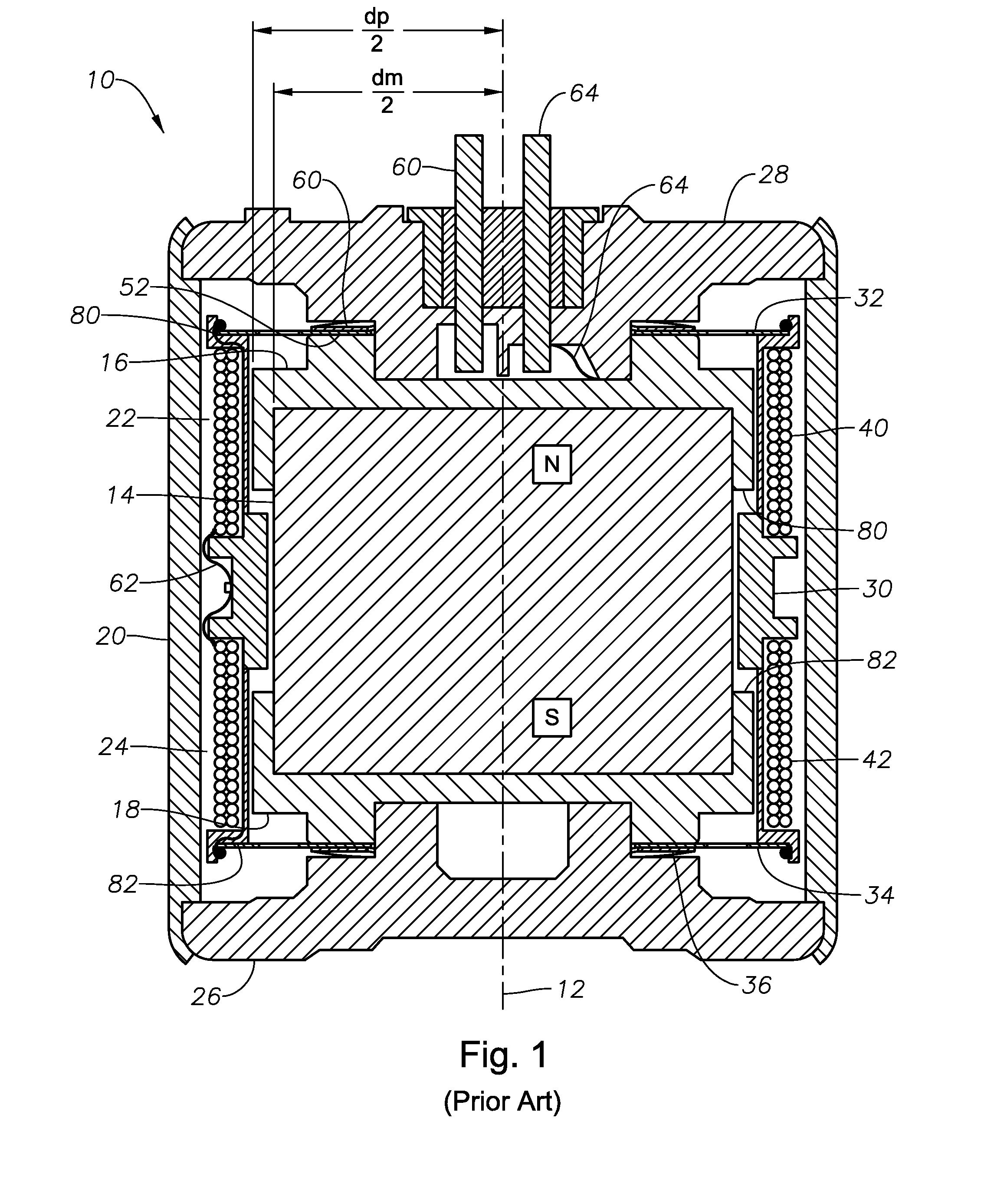
Moreover, tuning the geophone frequency response by control of the lower frequency spring 34 is made more difficult because of the serial spring-spring arrangement.
However, these design do not employ the lower frequency spring as an electrical circuit element.
Thus, the bobbin and coil assembly have a limited ability to rotate within the geophone housing, which can result in damage to the geophone if it is subjected to rough handling during deployment or retrieval, for example.

Method used


Image

  • Vertical geophone having improved distortion characteristics
  • Vertical geophone having improved distortion characteristics
  • Vertical geophone having improved distortion characteristics

Examples


Embodiment Construction

[0037]FIG. 3 illustrates an improved geophone 110 according to an embodiment of the invention, which for a given magnet type and geometry may have a greater sensitivity than geophone 10 (FIG. 1) of prior art. FIG. 3 is drawn to the same scale as FIG. 1. FIG. 4 is a cut away view in partial cross-section of geophone 110 of FIG. 3, shown without bobbin 130 and coils 122, 124 for simplicity. FIG. 5 is a side-by-side comparison of geophone 110 with prior art geophone 10. On the left side FIG. 5, a cross section of the typical geophone 10 of FIG. 1 is shown. On the right side, a geophone 110 of FIG. 3 and according to an embodiment of the invention is shown. The two geophone drawings 10, 110 are illustrated in the same scale and positioned along a common centerline so that a comparison may be readily made.

[0038]Referring to FIGS. 3-5, as compared to prior art geophone 10 of FIG. 1, geophone 110 is characterized by a parasitic flux leakage that is significantly reduced, because the lg dim...


PUM


Abstract

A vertical geophone that includes a lower frequency spring, which forms part of the geophone electrical circuit, that is positioned directly on the lower end cap This arrangement eliminates the “spring supported by a spring” arrangement of prior art geophones to minimize geophone distortion and simplify tuning of the frequency springs. A contact spring is positioned between the lower frequency spring and the lower pole piece for forming part of the geophone electrical circuit. One surface of contact spring includes a plurality of wiper surfaces that ensure consistent sliding electrical contact against either the bottom surface of the lower pole piece or the upper surface of the lower frequency spring. The obverse surface of the contact spring is preferably spot welded to the other adjacent member.

Description

BACKGROUND OF THE INVENTION[0001]1. Field of the Invention[0002]This invention relates generally to geophones used in seismic exploration.[0003]2. Description of the Prior Art[0004]FIG. 1 shows a vertical geophone 10 of conventional design. FIG. 1 is a cross section taken along the longitudinal axis 12 of the geophone 10. Geophone 10 employs a cylindrical magnet 14, cylindrical upper and lower ferrous pole pieces 16, 18, and a tubular ferrous outer housing 20, which together form a magnetic circuit.[0005]Upper and lower pole pieces 16, 18 each have a cap-like shape so that they fit over and receive the upper and lower ends of magnet 14, respectively. The tubular portion of the upper and lower pole pieces that enclose the sides of cylindrical magnet 14 are referred to herein as the pole piece lips 80, 82. Magnet 14 and pole pieces 16, 18 are received within outer cylindrical housing 20. An upper annular air gap 22 exists between upper pole piece 16 and outer housing 20, and a lower a...

Claims


Application Information

Patent Timeline
Patent Type & Authority Applications(United States)
IPC IPC(8): H04R9/00
CPCG01V1/182
Inventor WOO, DANIEL M.
Owner GEOSPACE TECH
Why Eureka
Try Eureka