Fluid interface cartridge for a microfluidic chip

a microfluidic chip and cartridge technology, applied in the field of microfluidic devices and systems, can solve the problems of high cost, limited chip capacity, and high cost of point-of-care testing facilities, and achieve the effect of maintenance costs, reducing the cost of operation, and increasing the cost of operation

Inactive Publication Date: 2011-01-13
CANON US LIFE SCIENCES INC
View PDF2 Cites 65 Cited by
  • Summary
  • Abstract
  • Description
  • Claims
  • Application Information

AI Technical Summary

Benefits of technology

[0014]Aspects of the invention are embodied in an interface cartridge providing a fluid flow network for delivering fluid to inlet ports of a microfluidic assay chip having a plurality of microfluidic channels, each microfluidic channel having an inlet port for delivering fluid to a proximal end of the microfluidic channel and an outlet port for removing fluid from a terminal end of the microfluidic channel. The interface cartridge includes a cartridge body having formed therein a plurality of fluid delivery channels in fluid-communication with a one or more microfluidic channels in the microfluidic assay chip. The cartridge body further includes a delivery interface configured to fluidly couple the fl...

Problems solved by technology

As a consequence, because the wells are much larger than the process channels, the chip capacity (i.e., the number of microfluidic process channels on the microfluidic chip) is limited by the size of the wells rather than that of the process channels.
There are several challenges that exist in connection with the development of in-vitro dia...

Method used


Image

  • Fluid interface cartridge for a microfluidic chip
  • Fluid interface cartridge for a microfluidic chip
  • Fluid interface cartridge for a microfluidic chip

Examples


Embodiment Construction

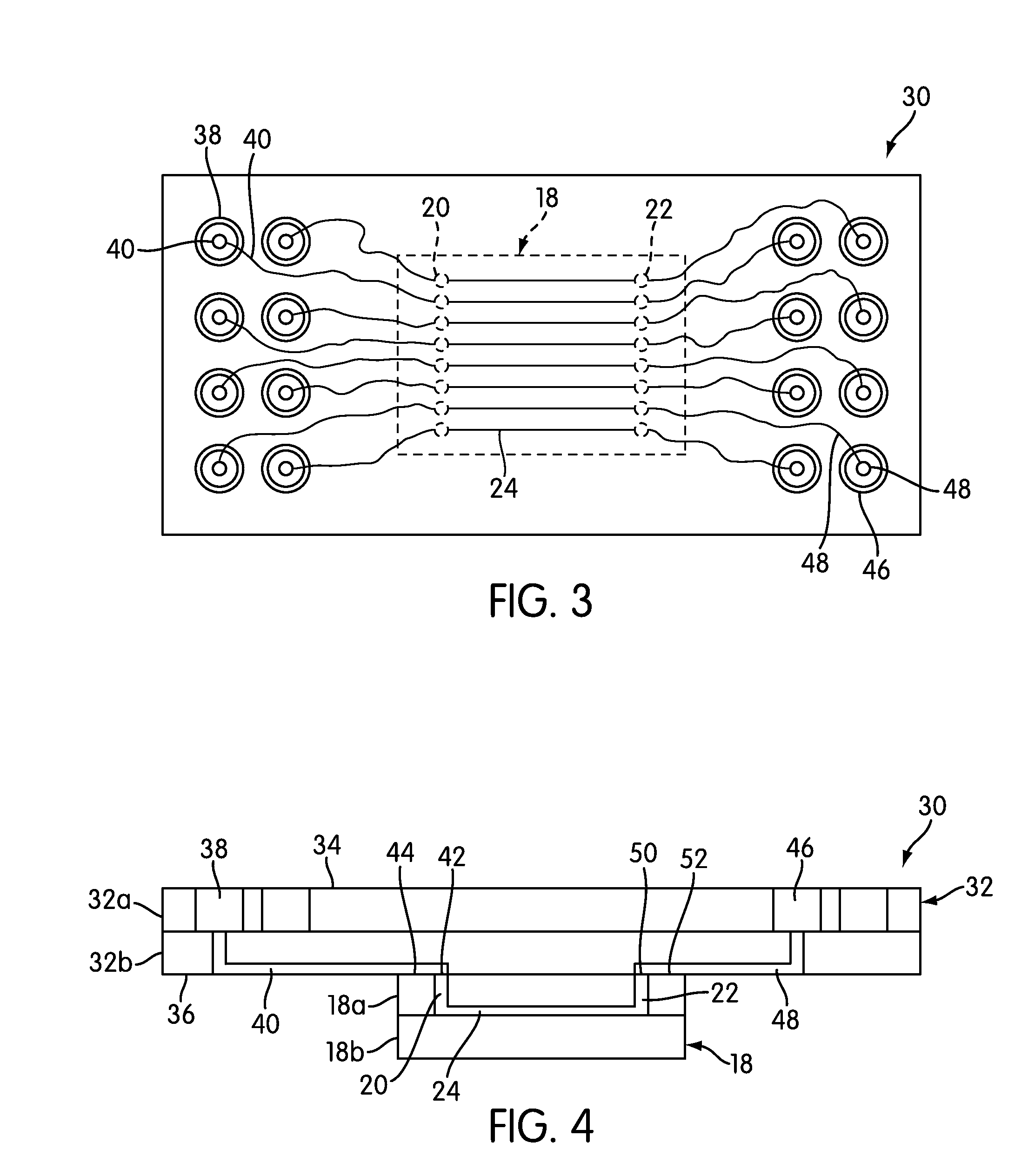
[0071]The present invention provides secondary, interface cartridges or chips, referred to herein as interface cartridges, which enable the use of greater numbers or quantities of reagents, samples, and other materials without being limited by the configuration or space available on a traditional microfluidic chip.

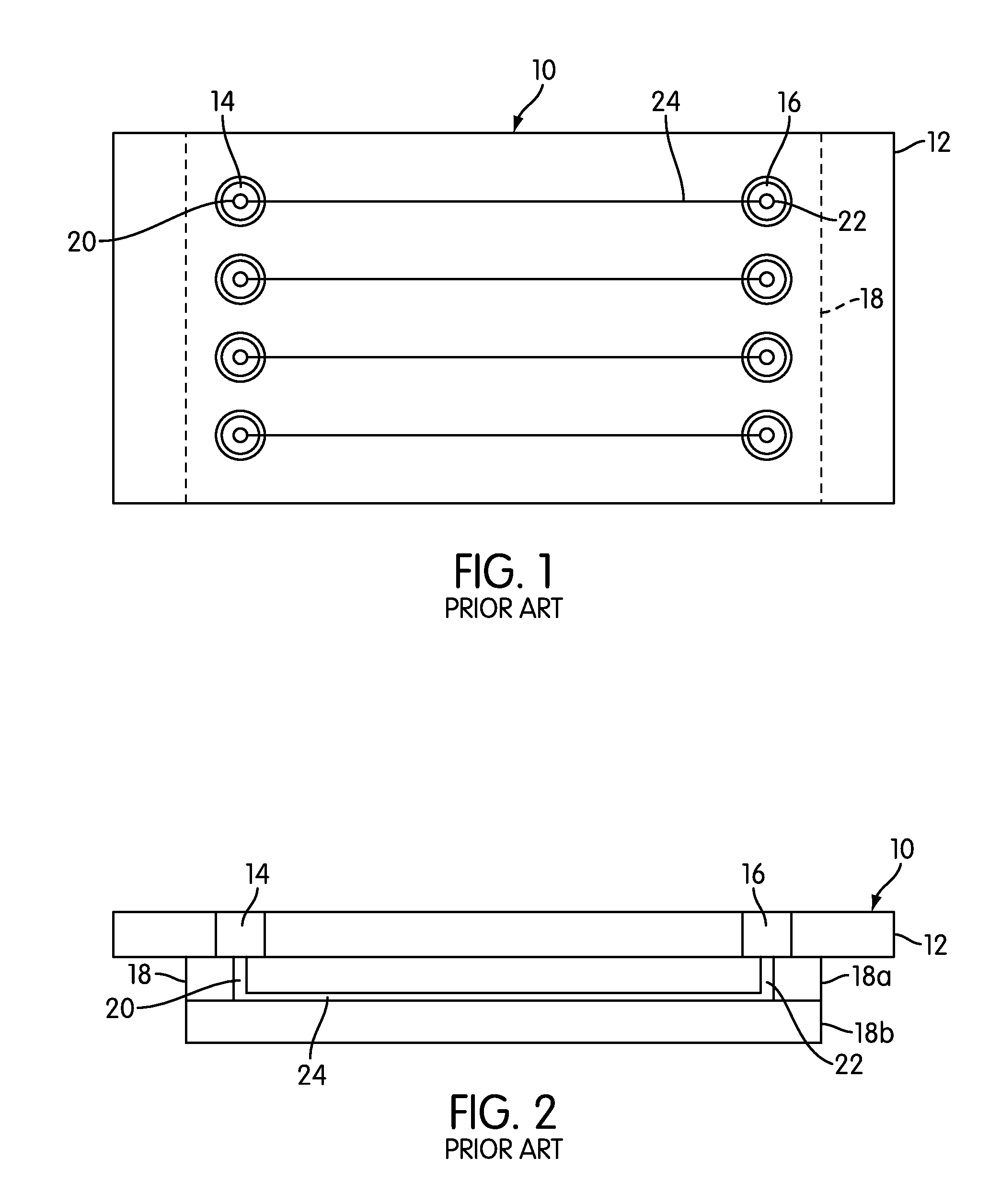
[0072]An assembly of an interface cartridge and a microfluidic chip embodying aspects of the present invention is designated generally by reference number 30 in FIGS. 3-4. Assembly 30 includes a microfluidic chip 18 coupled to an interface cartridge 32 embodying aspects of the present invention. Microfluidic chip 18 may be formed of, for example, glass, silica, or quartz, and may include an upper layer 18a and a lower layer 18b. Microfluidic chip 18 further includes microfluidic process channels 24 with an inlet port 20 and outlet port 22 disposed on opposite ends of each microfluidic process channel. A portion of each microfluidic chip 24 may comprise a thermal melt regio...


PUM


Abstract

An interface cartridge for a microfluidic chip, with microfluidic process channels and fluidic connection holes at opposed ends of the process channels, provides ancillary fluid structure, including fluid flow channels and input and/or waste wells, which mix and/or convey reaction fluids to the fluidic connection holes and into the process channels of the microfluidic chip.

Description

PRIORITY CLAIM[0001]This application claims the benefit under 35 U.S.C. 119(e) of U.S. Provisional Application No. 61 / 168,468, filed Apr. 10, 2009, the disclosure of which is hereby incorporated by reference in its entirety.BACKGROUND[0002]1. Field of the Invention[0003]The present invention relates to microfluidic devices and systems and, more specifically, to microfluidic devices and systems that include the use of external chips or cartridges that fluidically interface with microfluidic chips having one or more microfluidic channels.[0004]2. Description of Related Art[0005]Microfluidic chips are being developed for “lab-on-a-chip” devices to perform in-vitro diagnostic testing, including nucleic acid diagnostic assays, such as Polymerase Chain Reaction (“PCR”). The largest growth area for the use of such devices is in the field of molecular biology, where DNA amplification is performed in the sealed channels (“process channels”) of the microfluidic chip. In one type of diagnostic...

Claims


Application Information

Patent Timeline
IPC IPC(8): B01L3/00
CPCB01L3/502715B01L9/527B01L2200/021G01N2035/1034B01L2300/0816G01N35/1095B01L2200/027B01L3/502723B01L2300/0867
Inventor TSAO, RAYINOUE, HIROSHIZENG, SHULINMURPHY, BRIANHASSON, KENTON C.
Owner CANON US LIFE SCIENCES INC
Why Eureka
Try Eureka