Planetary gear

a technology of planetary gear and gearing, which is applied in the direction of gearing, toothed gearing, belt/chain/gearing, etc., can solve the problem of not having a sufficient high gear ratio, and achieve the effect of reducing the number of rubbing surfaces, high gear ratio, and maximum efficiency

Inactive Publication Date: 2011-01-13
KAPELEVICH ALEXANDER
View PDF9 Cites 18 Cited by
  • Summary
  • Abstract
  • Description
  • Claims
  • Application Information

AI Technical Summary

Benefits of technology

[0015]It has only two stages. This allows to have low number of gears and other components (shafts, bearings, carriers, etc.). This also reduces number of rubbing surfaces increasing gear efficiency.
[0016]The high gear ratio does not depend on number of planets in each stage. This allows selecting more planets per stage to transmit maximum load.
[0017]Gear tooth profiles of each stage are designed independently. This allows optimizing gear tooth profiles for minimum specific sliding velocities and maximum efficiency.
[0018]The high gear ratio does not require low number of teeth of the sun gears in each stage. This allows selecting more planets per stage to transmit maximum load. This allows reducing specific sliding velocities and increase efficiency.

Problems solved by technology

However, it does not have a sufficient high gear ratio (the input shaft angular speed divided on the output shaft angular speed) from 100:1 to 100,000 and more

Method used


Image

  • Planetary gear
  • Planetary gear
  • Planetary gear

Examples


first embodiment

FIGS. 1-3, 7

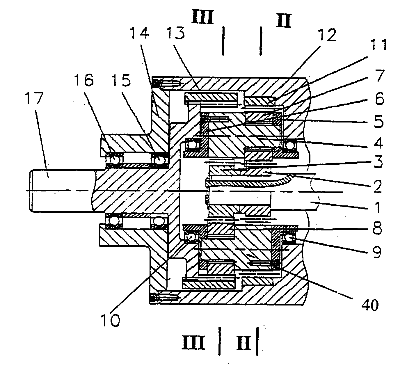
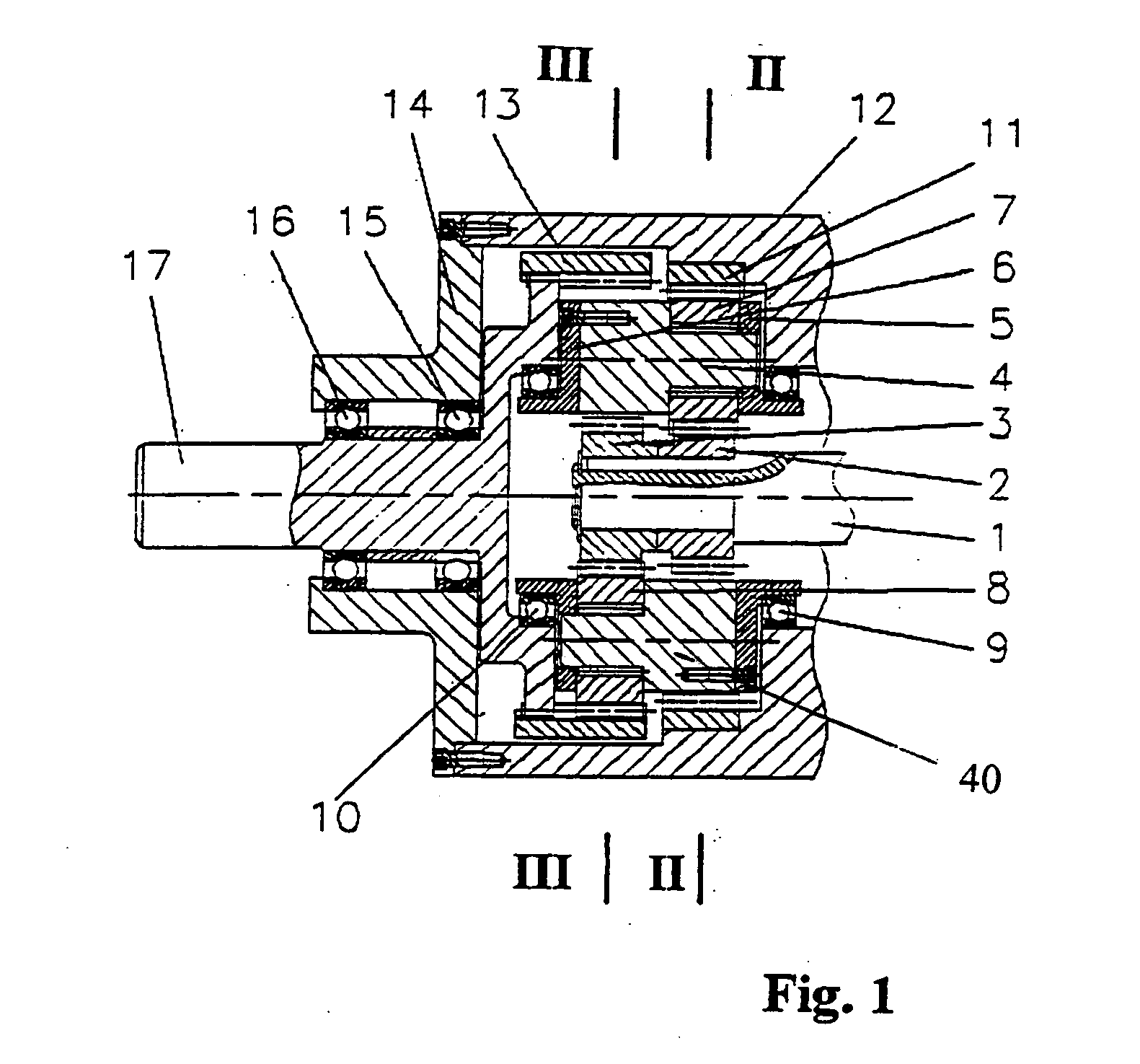
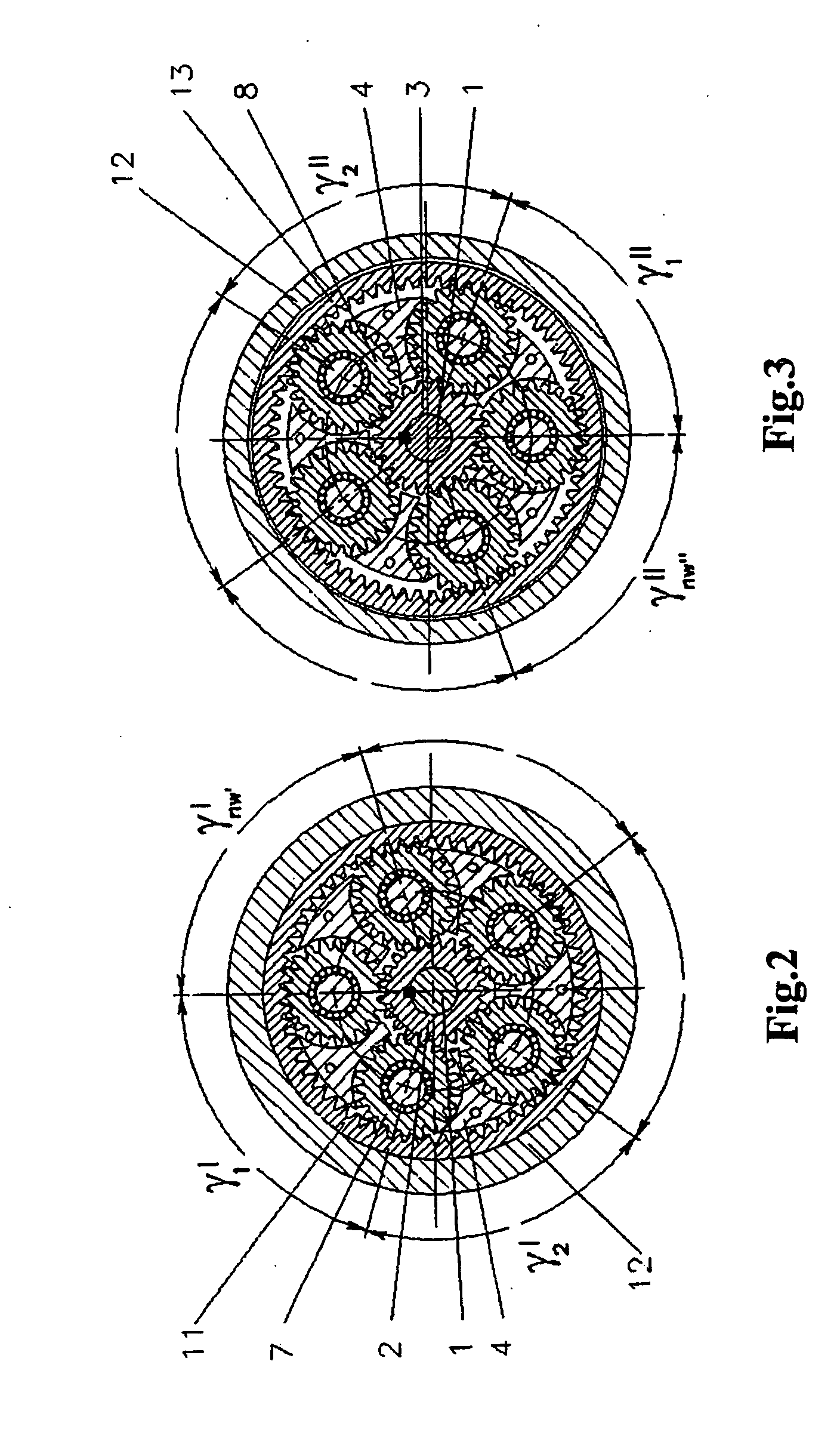
[0029]The first and second stage sun gears 2 and 3 are rigidly connected to the input shaft 1. The first stage sun gear 2 is engaged with the first stage planet gears 7. The first stage planet gears 7 are rotating on the bearings or bushings on the shafts that are rigidly connected or made as one piece with the carrier 4. The first stage planet gears 7 are constrained in axial direction by the back carrier flange 5, which is rigidly connected to the carrier 4. The back carrier bearing 9 that is pressed into to the gear housing 12 supports the back carrier flange 5. The first stage planet gears 7 are engaged with the first stage crown gear 11. The first stage crown gear 11 is unmovable and rigidly connected to the gear housing 12. The second stage sun gear 3 is engaged with the second stage planet gears 8. The second stage planet gears 8 are rotating on the bearings or bushings on the shafts that are rigidly connected or made as one piece with the carrier 40. The second s...

second embodiment

FIGS. 4-6, 8

[0038]The first and second stage sun gears 2 and 3 are rigidly connected to the input shaft 1. The first stage sun gear 2 is engaged with the first stage planet gears 7. The first stage planet gears 7 are rotating on the bearings 18 on the shafts 19 that are rigidly connected (pressed in) or made as one piece with the carrier 4. The first stage planet gears 7 are engaged with the first stage of the crown gear 11. The second stage sun gear 3 is engaged with the second stage planet gears 8. The second stage planet gears 8 are rotating on the bearings 20 on the shafts 21 that are rigidly connected (pressed in) or made as one piece with the carrier 40 that is rigidly connected or made as one piece with the output shaft 17. The second stage planet gears 8 are engaged with the crown gear 13 of the second stage. The first stage of the crown gear 11 and the second stage of the crown gear 13 are rigidly connected or made as one piece.

[0039]The input shaft 1 transmits rotation by ...


PUM


Abstract

A planetary gear drive comprises two stages. Each of two stages comprises a central sun gear, a crown gear, several satellites located on a carrier between the sun gear and the crown gear, input and output shafts. The sun gear of the first and second stages is rigidly connected to each other. The input shaft is rigidly connected with the sun gear of the first stage. The carriers of the first and the second stages are rigidly connected to each other and, the output shaft is rigidly connected with the crown gear of the second stage (first embodiment). The crown gears of the first and the second stages are rigidly connected to each other, and the output shaft is rigidly connected with the carrier of the second stage (second embodiment).The satellites are at least at one stage are unevenly distributed around.

Description

[0001]This application claims priority from U.S. Provisional Application 61 / 224,931 filed Jul. 13, 2009, the entire disclosure of which is incorporated herein by referenceBACKGROUND OF THE INVENTION[0002]1. Field of the Invention[0003]This invention relates to planetary gear, and in particular to planetary gear for applications requiring high gear ratio (the input shaft angular speed divided on the output shaft angular speed) from 100:1 to 100,000:1 and more.[0004]2. Discussion of the Prior Art[0005]It is known in the art examples of planetary gear drives. For example the planetary gears described in U.S. Pat. Nos. 1,632,123 and 1,998,891. An advantage of the planetary gear drive having the configuration described in the above disclosure is that it enables a compact drive configuration. However, it does not have a sufficient high gear ratio (the input shaft angular speed divided on the output shaft angular speed) from 100:1 to 100,000 and moreSUMMARY OF THE INVENTION[0006]In view of...

Claims


Application Information

Patent Timeline
IPC IPC(8): F16H57/08
CPCF16H37/041F16H1/46F16H1/06
Inventor KAPELEVICH, ALEXANDER
Owner KAPELEVICH ALEXANDER
Why Eureka
Try Eureka