
Sensor housing assembly facilitating sensor installation, replacement, recovery and reuse

a technology for sensors and housings, applied in the direction of measuring devices, measuring apparatus components, instruments, etc., can solve the problems of sensor destruction, no epoxy use, sensor recovery attempts, etc., and achieve the effect of facilitating sensor recovery

Inactive Publication Date: 2011-01-20
AMERICAN TRAFFIC SOLUTIONS
View PDF12 Cites 29 Cited by
  • Summary
  • Abstract
  • Description
  • Claims
  • Application Information

AI Technical Summary

Benefits of technology

[0012]An enclosed sensor assembly for essentially permanent mounting within a road flush with the top surface thereof, has a housing a sensor and an upper cover. The housing has a flat bottom portion; first side wall portions and second side wall portions. The first side wall portions are attached to the flat bottom portion at the periphery thereof, which, together with the flat bottom portion, defines a sensor enclosing pocket having an upper interface portion. The second side wall portions are attached to the first side wall portions and laterally extend from the first side wall portions so as to define at least one lateral epoxy receiving pocket. Optionally, dead spaces adjacent the sensor pocket are provided which help isolate the sensor pocket against entry of epoxy. The sensor installs in the sensor pocket. The cover has an upper cover interface abutting against the upper interface portion to substantially enclose the sensor enclosing pocket.

Problems solved by technology

As a result, sensor removal is likely to cause sensor destruction.
However, there is no epoxy use at all discussed here, probably should not be used here because of the need that the cover remain permeable.
Using known prior art technology, recovery attempts for sensors often fail because the sensor is embedded in epoxy or epoxy used to fix the sensor often seeps into the housing, contaminating the label or making intact removal of the sensor impossible.
Whether or not successful, the removal attempt requires about one and a half hours per sensor.

Method used


Image

  • Sensor housing assembly facilitating sensor installation, replacement, recovery and reuse
  • Sensor housing assembly facilitating sensor installation, replacement, recovery and reuse
  • Sensor housing assembly facilitating sensor installation, replacement, recovery and reuse

Examples


Embodiment Construction

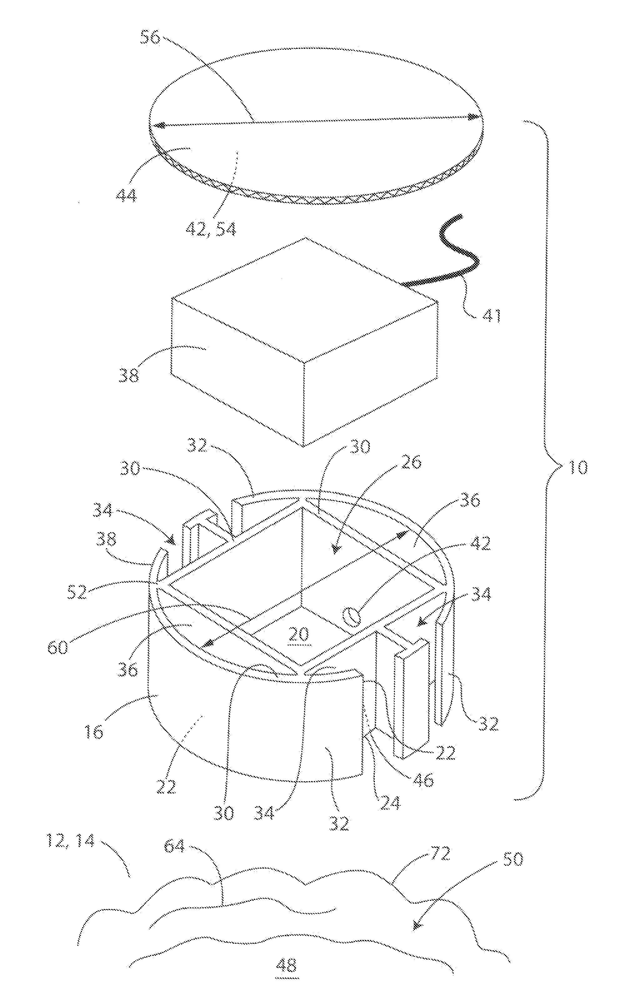
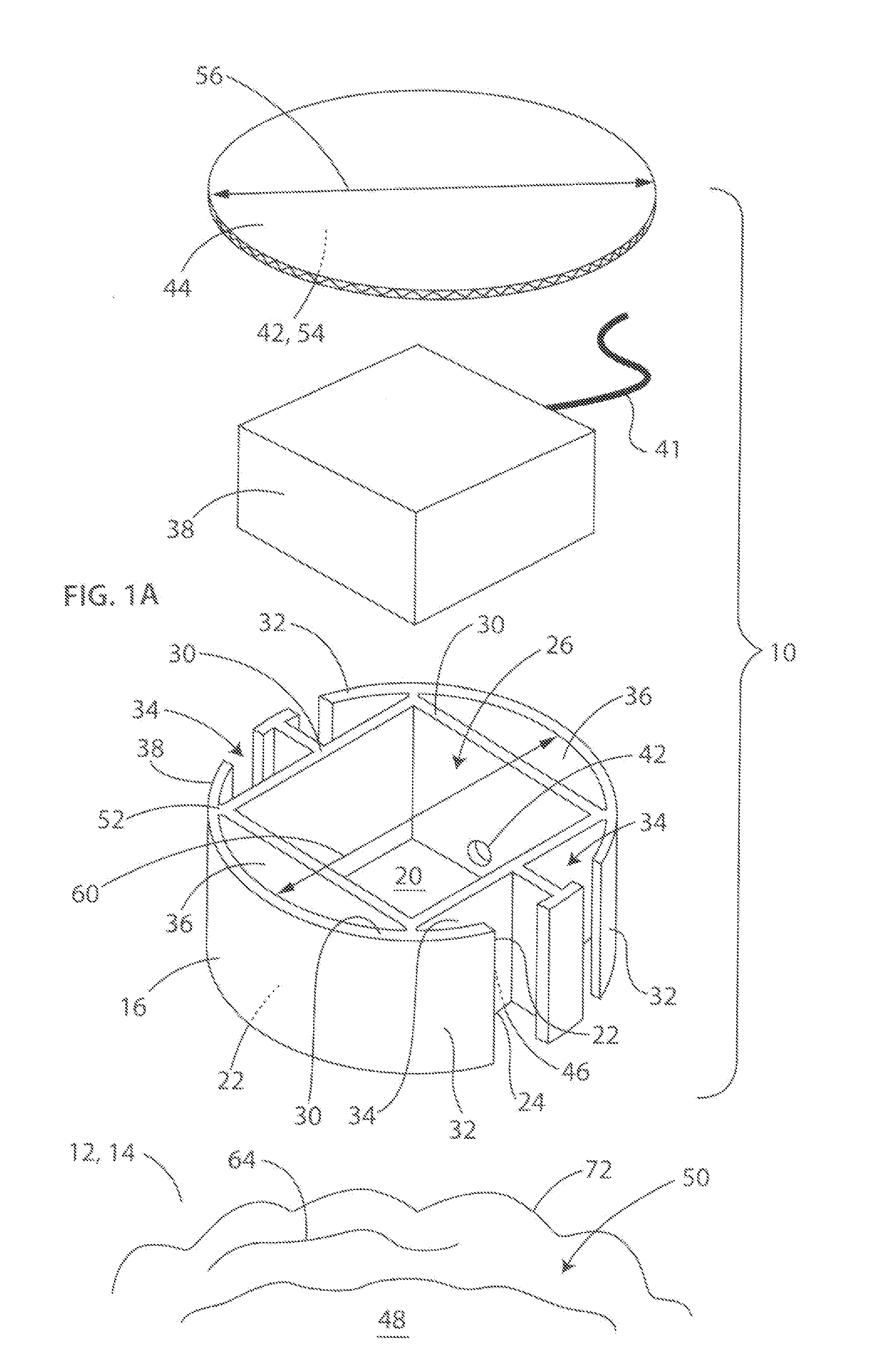
[0033]The following description is not intended to limit the scope of the invention in any way as they are exemplary in nature and serve to describe the best mode of the invention known the inventors as of the filing date hereof. Consequently, changes may be made in the arrangement and / or function of any of the elements described in the disclosed exemplary embodiments without departing from the spirit and scope of the invention.

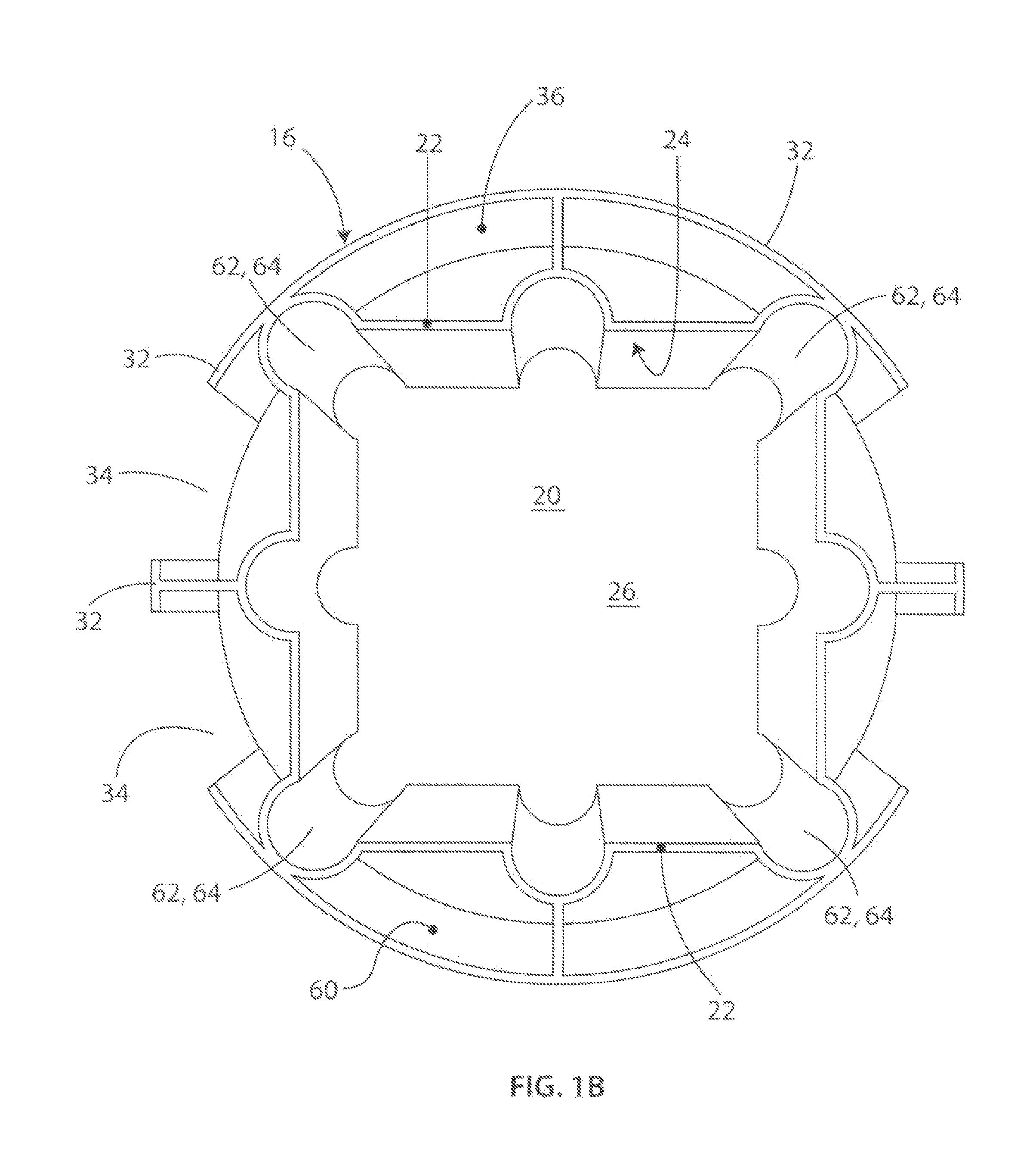
[0034]Referring now to FIG. 1A, an enclosed sensor assembly 10 for essentially permanent mounting within a road 12 flush with the top surface 14 thereof, has a housing 16, a sensor 38 and an upper cover 44. The housing 16 has a flat bottom portion 20, first side wall portions 22 and second side wall portions 32. The first side wall portions 22 are attached to the flat bottom portion 20 at the periphery 24 thereof, which, together with the flat bottom portion, defines a sensor enclosing pocket 26 having an upper interface portion 30. The second side wall porti...


PUM


Abstract

An enclosed sensor assembly (10) for permanent mounting within a road (12) flush with the top surface (14) thereof, has a housing 16, a sensor 38 and an upper cover (44). The housing (16) has a flat bottom portion (20); first side wall portions (22) and second side wall portions (32). The first side wall portions (22) are attached to the flat bottom portion (20) at the periphery (24) thereof, which, together with the flat bottom portion, defines a sensor enclosing pocket (26) having an upper interface portion (30). The second side wall portions (32) are attached to the first side wall portions (22) and laterally extend from the first side wall portions so as to define at least one lateral epoxy receiving pocket (34). Optionally, dead spaces (36) adjacent the sensor pocket (26) are provided which help isolate the sensor pocket against entry of epoxy (30). The sensor (38) installs in the sensor pocket (26). The cover (44) has an upper cover interface (42) abutting against the upper interface portion (30) to substantially enclose the sensor enclosing pocket (26).

Description

CROSS REFERENCE TO RELATED APPLICATIONS[0001]This application claims the benefit of U.S. Provisional Application No. 61 / 226,319, filed 17 Jul. 2009, the content of which is incorporated by reference hereto.COPYRIGHT & LEGAL NOTICE[0002]A portion of the disclosure of this patent document contains material which is subject to copyright protection. The copyright owner has no objection to the facsimile reproduction by anyone of the patent document or the patent disclosure as it appears in the Patent and Trademark Office patent file or records, but otherwise reserves all copyright rights whatsoever. Further, no references to third party patents or articles made herein is to be construed as an admission that the present invention is not entitled to antedate such material by virtue of prior invention.BACKGROUND OF THE INVENTION[0003]This invention relates to a method of installation of a sensor in a road surface and the sensor assembly for use in such method.[0004]Electronic sensors are a ...

Claims


Application Information

Patent Timeline
Patent Type & Authority Applications(United States)
IPC IPC(8): G01D11/24
CPCG01D11/245G08G1/042
Inventor WILSON, JOHN
Owner AMERICAN TRAFFIC SOLUTIONS
Learn More