Lock unit having a slotted pawl

a locking unit and slotted technology, applied in the field of door latches, can solve the problems of damage to the locking unit, noise and actuation force caused by opening the vehicle door, and the occupant of the moving vehicle is a danger, so as to reduce the size and manufacturing cost, simplify the design, and minimize noise and actuation for

Active Publication Date: 2011-01-20
KIEKERT AG
View PDF12 Cites 78 Cited by
  • Summary
  • Abstract
  • Description
  • Claims
  • Application Information

AI Technical Summary

Benefits of technology

[0007]In order to reduce size and manufacturing costs, the primary and secondary latched positions of a lock unit should reside on the same plane as the catch. Further, providing a single blocking arm of a single pawl to achieve the primary and secondary latched positions helps to further simplify the design and ensure consistent operation. However, the lock unit should still utilize a smooth release of locking surfaces to minimize noise and actuation forces. In addition, the design should take into account manufacturing tolerances such that minor dimensional variations will not adversely effect the performance of the lock unit.
[0008]In an embodiment, the present invention provides a lock unit having a pawl disposed intermediate a catch and a blocking lever. The catch is rotatable and biased in an opening direction about a catch rotation axis toward an open position of the lock unit in which a first recess of the catch is configured to receive a striker of the vehicle. Additionally, the catch includes a second recess disposed before the first recess in the opening direction. The pawl includes a slot rotatable about a fixed pawl pivot axis and is biased toward both the catch and the pawl pivot axis. Further, the pawl includes a blocking arm which extends into the second recess of the catch when the lock unit is in a secondary latched position. The blocking lever abuts the blocking arm of the pawl against the catch in a primary latched position of the lock unit. When the lock unit is forced from the secondary latched position to the primary latched position, opposite the opening direction of the catch, the pawl moves in a longitudinal direction of the slot and avoids displacement of the blocking lever.

Problems solved by technology

This secondary latched position falls between the primary latched position and the open position such that if the catch fails to reach the primary latched position, the door will be retained shut in the secondary latched position rather than moving all the way to the open position, which would obviously be dangerous to an occupant of a moving vehicle.
Owing to the high forces biasing the locking surfaces of the pawl and catch against one another (and also biasing the catch toward the limit stop), the noises caused by opening the vehicle door are quite loud.
Additionally, the high impacts on the pawl and catch can cause damage to the lock unit and severely limit its useful life, especially since most of the impact occurs along the locking surfaces.
However, because the locking surfaces are designed to slide relatively easily with respect to one another, the latching mechanism is not self-latching (i.e., the locking surfaces do not hold the catch in place on their own) and requires a pawl blocking lever to hold the first pawl against the catch in the primary latched position.
Providing the second pawl on a different plane and the introduction of the bolt into the catch can be costly from a manufacturing standpoint, however.
Thus, while the multi-pawl design effectively reduces opening noise and latch actuation forces, it requires multiple different components at multiple planes of the latching mechanism, thereby making the device relatively complex and expensive to manufacture.

Method used


Image

  • Lock unit having a slotted pawl
  • Lock unit having a slotted pawl
  • Lock unit having a slotted pawl

Examples


Embodiment Construction

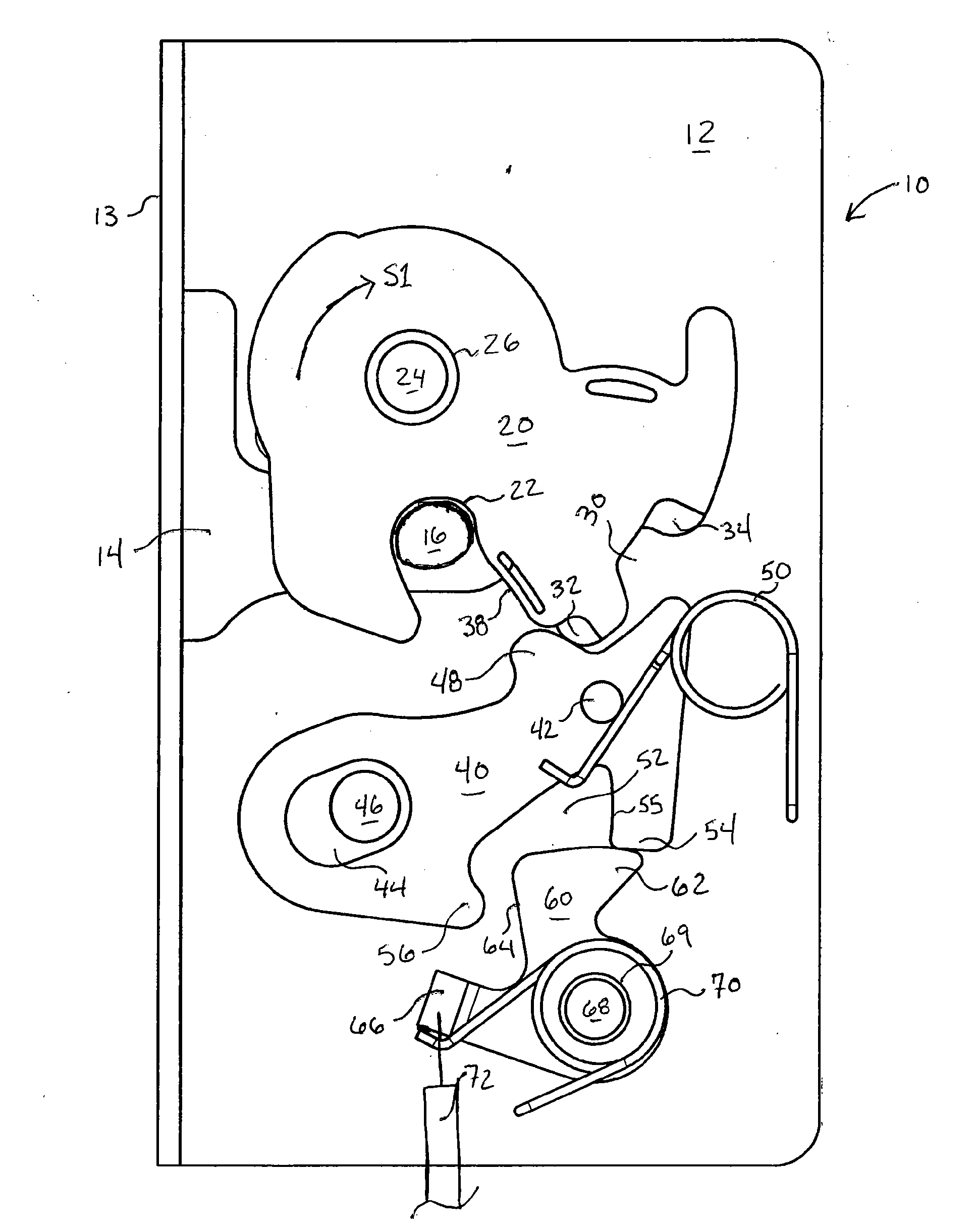
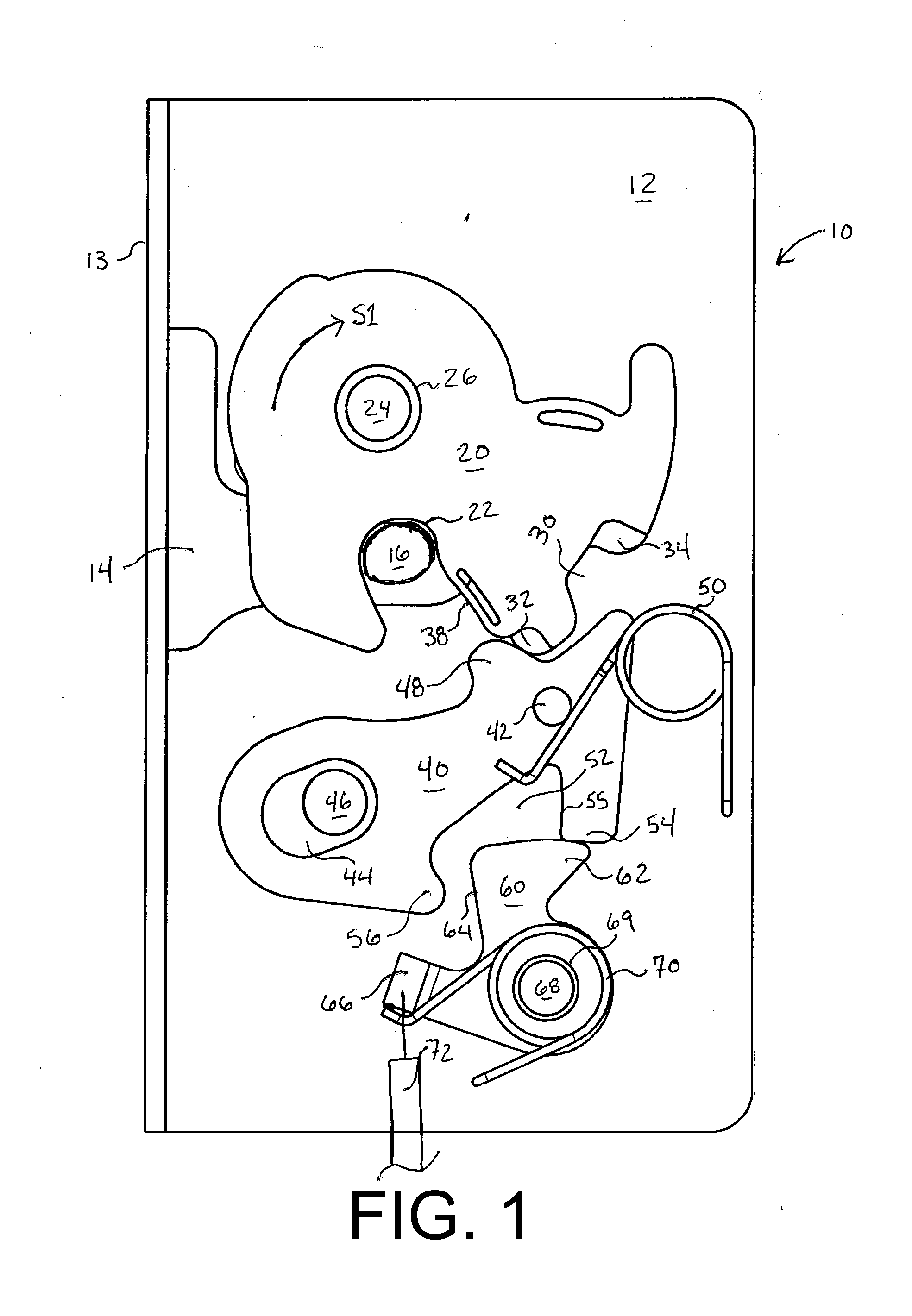
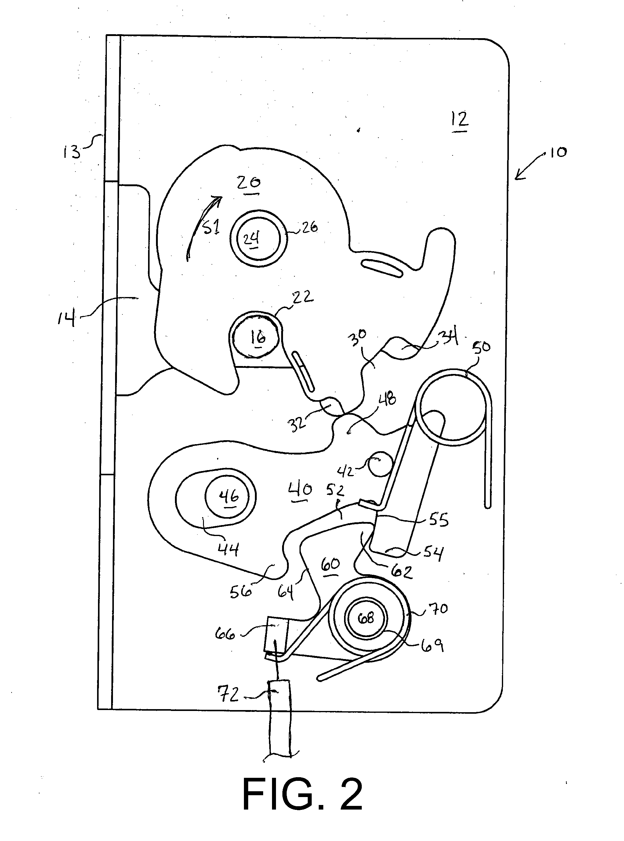
[0017]Referring to FIGS. 1 and 3, a lock unit 10 according to an embodiment of the present invention is shown in the primary latched position and the open position, respectively. The lock unit 10 includes a baseplate 12 for mounting the lock unit 10 to a door, hatch or tailgate of a vehicle with a slot 14 facing a striker 16 mounted to the vehicle body. Typically, the striker 16, or catch bolt, is a pin or U-shaped bracket mounted to a partition at the rear side of the vehicle doorframe and extending into the plane of the door opening. The lock unit 10 is typically mounted opposite the vehicle door hinges with the leading edge 13 of the baseplate 12 facing the striker 16 and the components of the lock unit 10 being disposed in the vehicle door. With such a configuration, as the vehicle door is shut, the striker 16 extends into the slot 14 of the baseplate 12 and into a first recess 22 of a catch 20 to rotate the catch 20 from an open position (FIG. 3) to a primary latched position (...


PUM


Abstract

A lock unit for a vehicle includes a rotatable catch biased in an opening direction about a catch rotation axis toward an open position of the lock unit in which a first recess of the catch is configured to receive a striker of the vehicle. Additionally, the catch includes a second recess disposed before the first recess in the opening direction. A pawl including a slot rotatable about a fixed pawl pivot axis is biased toward both the catch and the pawl pivot axis. The pawl includes a blocking arm which extends into the second recess of the catch when the lock unit is in a secondary latched position. A blocking lever of a ratchet abuts the blocking arm of the pawl against the catch in a primary latched position of the lock unit preventing rotation of the pawl away from the catch. When the lock unit is forced from the secondary latched position to the primary latched position, the pawl moves in a longitudinal direction of the slot avoiding the rotational blocking action of the ratchet.

Description

FIELD OF THE INVENTION[0001]The present invention relates generally to door latches, and more specifically to a lock unit for the door of a vehicle utilizing a pawl having a slot mounted on a fixed pawl pivot axis.BACKGROUND OF THE INVENTION[0002]Lock units customarily used for side-doors of motor vehicles utilize a latching mechanism, known as a catch, which receives a catch-bolt, or striker, disposed on a pillar of the vehicle doorframe. The catch is biased to an open position wherein a slot of the latch housing is aligned with a recess of the catch. As the door is shut, the striker enters the recess through the slot and rotates the catch to a closed position in which the striker is retained in the recess by a pawl which prevents the catch from rotating toward the open position. Typically the pawl is heavily biased towards the catch with the interface of the two comprised of a further negative biased angle to resist high acceleration forces. The latch housing is typically made of ...

Claims


Application Information

Patent Timeline
Patent Type & Authority Applications(United States)
IPC IPC(8): E05C3/06
CPCE05B85/26Y10S292/62E05B77/36Y10T292/1047
Inventor HUNT, ROBERTZHUANG, JIMPOHLE, WERNER
Owner KIEKERT AG
Why Eureka
Try Eureka