Capacitive sensor array

Inactive Publication Date: 2011-01-20
HUF HULSBECK & FURST GMBH & CO KG
View PDF6 Cites 45 Cited by
  • Summary
  • Abstract
  • Description
  • Claims
  • Application Information

AI Technical Summary

Benefits of technology

[0008]It was shown that when a space was specifically created between the plastic layer that forms the contaminated outer surface and the plastic layer that surrounds the sensor electrode with a dielectricity constant that approximates the value of 1, it was possible to reduce or avoid the interfering influences of moisture

Problems solved by technology

It has been shown that when such a capacitive sensor array is used in an environment that is burdened with dirt and humidity, e.g. on the exterior of a motor vehicle (e.g. as a proximity sensor in an exterior door handle), undesired capacity changes may occur due t

Method used


Image

  • Capacitive sensor array
  • Capacitive sensor array
  • Capacitive sensor array

Examples


Embodiment Construction

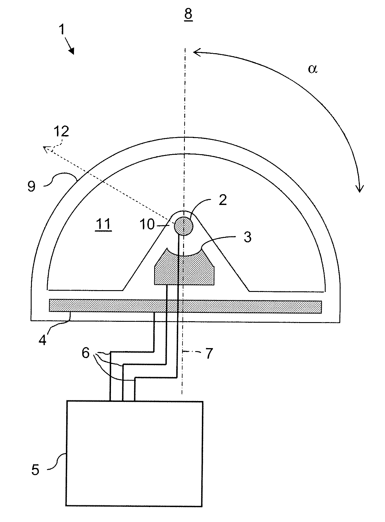
[0021]FIG. 1 shows a schematic depiction of a cross-section through a sensor array 1 in accordance with the invention with a connected control and evaluation circuit 5. The sensor array 1 is a profile that is extended longitudinally in the direction that is perpendicular to the diagram plane of FIG. 1. The sensor array 1 includes a sensor electrode 2 that extends longitudinally along a first coordinate line. The coordinate line progresses perpendicularly to the diagram plane of FIG. 1 and, for example, represents a coordinate line of a Cartesian coordinate system. The coordinate line does not have to be straight lined in other embodiments; it may also arch through space. For example the profile shown in FIG. 1 in section may be a flexible profile. The sensor electrode 2 has a circular cross-section in the exemplary embodiment shown in FIG. 1. In other exemplary embodiments, it may have a deviating, e.g. rectangular cross-section. A background electrode 4 is arrayed parallel to the s...


PUM


Abstract

A capacitive sensor array includes a sensor electrode, a shielding electrode and a background electrode which are surrounded by insulator materials and connected to a control and evaluation circuit. Using the sensor electrode that extends along a first coordinate line, the entry of an object into a space ahead of the sensor electrode is detected. The control and evaluation circuit detects a capacity change of the sensor electrode as compared to a reference potential. The shielding electrode is connected to the sensor electrode via the control and evaluation circuit in such a manner that its potential follows. The three electrodes are arranged behind each other along a second coordinate line that is perpendicular to the first coordinate line. The insulating materials are arrayed between the sensor electrode and the detection zone. The central axis of the cylinder lies within the plane that is formed by the first and second coordinate lines. The insulator materials between the detection zone and the sensor electrode include at least one plastic layer that directly surrounds the sensor electrode and a plastic layer that is arrayed at a specified distance. The insulator materials are arranged so that the relative dielectricity constant initially assumes a relatively high value of the surrounding plastic layer as the distance from the sensor electrode increases, then drops to a value that approaches the value of 1, and then again rises to a relatively high value of the outer plastic layer.

Description

BACKGROUND OF THE INVENTION[0001]A capacitive sensor array with a sensor electrode with whose aid the approach of an object is to be detected, and with a control and evaluation circuit that is linked to the sensor electrode and detects a capacity change of the sensor electrode as compared to mass by periodically linking the sensor electrode with an operating voltage at a predetermined frequency and evaluating at least one parameter of a current or voltage progression that is dependent on the periodic charging and discharging of the sensor electrode in order to detect the capacity change is, for example, known in the U.S. Pat. No. 5,730,165 as well as the corresponding patent document DE 196 81 725 B4. The parameter of a current or voltage progression that is dependent on the periodic charging and discharging of the sensor electrode herein consists of a voltage that can be measured over a condenser and depends on a charge that is accumulated in the condenser, wherein this charge is a...

Claims


Application Information

Patent Timeline
IPC IPC(8): G01R27/26
CPCH03K17/955B60R19/48
Inventor GASTEL, PETER VANLINDIC, IKO
Owner HUF HULSBECK & FURST GMBH & CO KG
Why Eureka
Try Eureka