Spectacles
a technology of spectacles and rims, applied in the field of spectacles, can solve the problems of glass material stiffness, glass material breakage, and increased difficulty in drilling holes thereon, and achieve the effects of reducing manufacturing difficulty, enhancing manufacturing efficiency, and enhancing the clipping force of the clipping member
- Summary
- Abstract
- Description
- Claims
- Application Information
AI Technical Summary
Benefits of technology
Problems solved by technology
Method used
Image
Examples
fifth embodiment
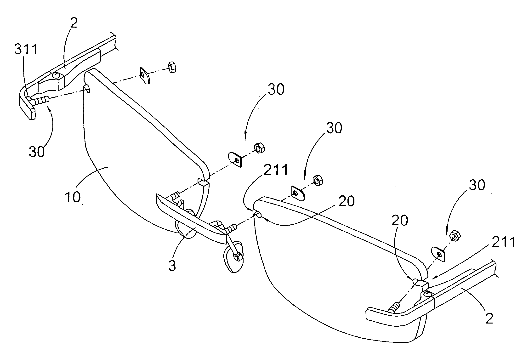
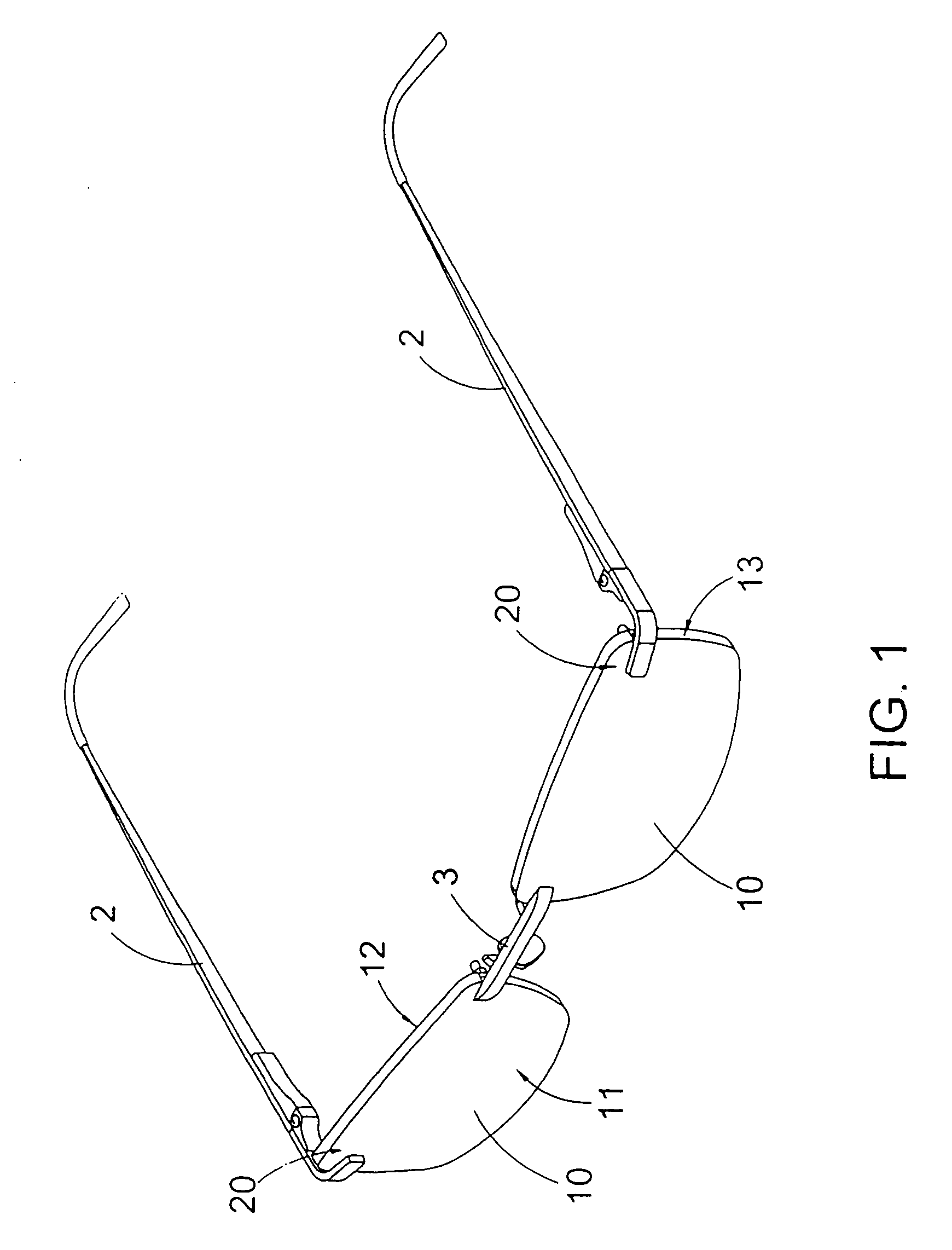
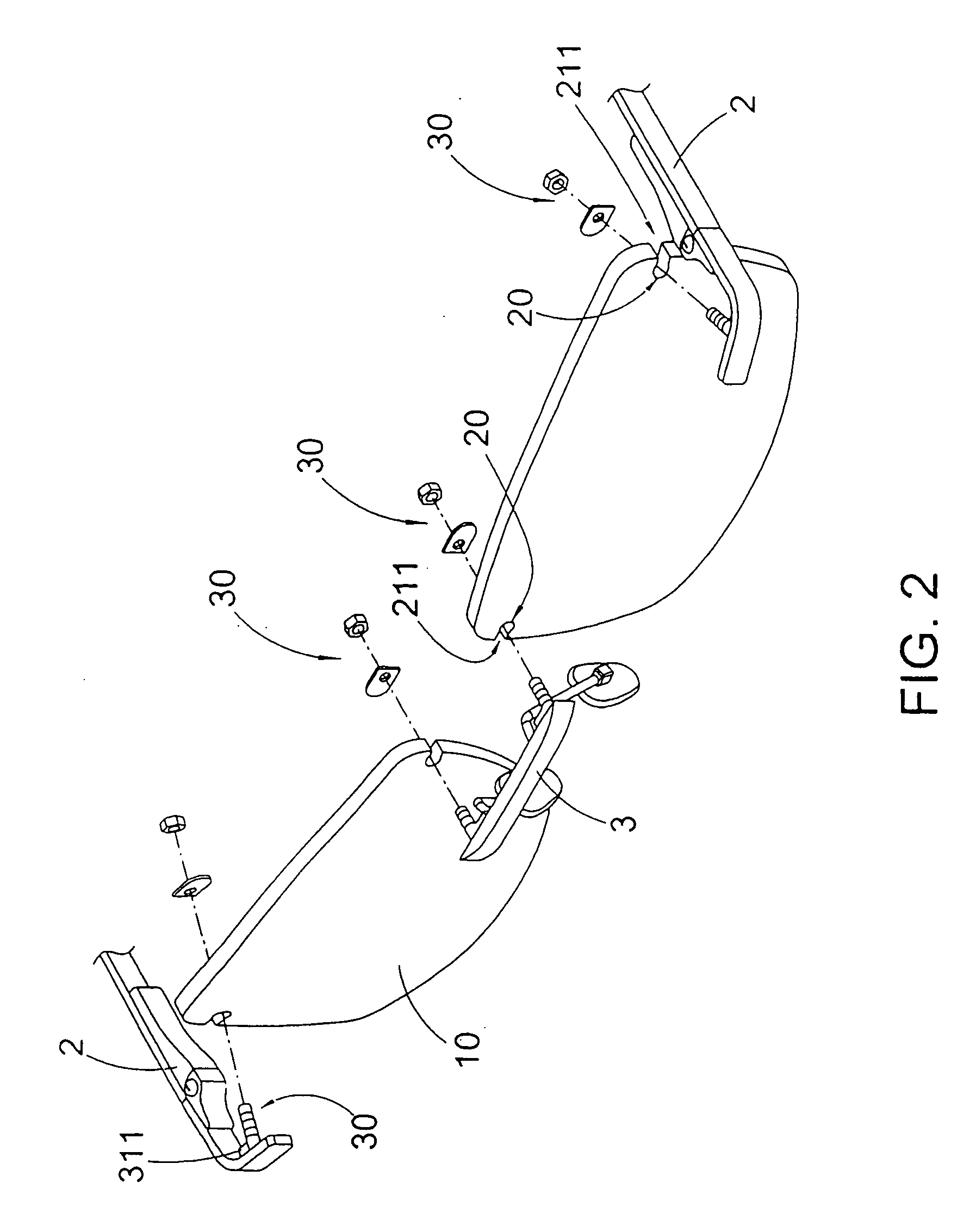
[0102]FIGS. 19 and 20 illustrate an alternative mode of the rimless spectacles of the fifth embodiment, wherein the second connectors 30D is adapted to incorporate with the first connector 20 as shown in FIG. 3. As shown in FIGS. 3, 19, and 20, each of the first connectors 20 is a coupling slot 20 indently formed at the peripheral edge 13 of the respective lens 10 to define the opening edges 21 and the coupling groove 25. As it is mentioned above, the distance between the two side surfaces 22 is larger than the distance between the two opening edges 21 such that the width of the opening 211 is smaller that the distance between the two side surfaces 22. Preferably the coupling groove 25 has a size slightly larger than the circumferential size of the elastic inserter 311D.
[0103]When the elastic inserter 311D is slidably passed through the respective coupling slot 20 at the front side of the lens 10, the enlarged head 3112D is located at the rear side of the lens 10. In particularly, t...
second embodiment
[0104]FIGS. 21 to 24 illustrate an alternative mode of the rimless spectacles of the As shown in FIGS. 21 to 24, each of the second connectors 30E comprises a connecting member 31E and a clipping member 32E, wherein the connecting members 31E are provided at the temple units2 and the bridge 3 respectively. Each of the connecting members 31A comprises a retention inserter 311E and a coupling shaft 312E, wherein the retention inserter 311E has a shape and size corresponding to the shape and size of the respective coupling slot 25. Each of the retention inserters 311E has a retention surface 3111E and a biasing surface 3112E, wherein the retention surface 3111E is shaped and sized corresponding to the curved contacting surface 24. When the retention inserter 311E is slidably inserted into the corresponding coupling slot 20 inwardly from the peripheral edge 13 of the lens 10, the retention surface 3111E of the retention inserter 311E is biased against the curved contacting surface 24 t...
sixth embodiment
[0109]FIGS. 25 to 27 illustrate an alternative mode of the spectacles of the sixth embodiment, wherein the spectacles is the rim-type spectacle incorporating with the connection mechanism. As shown in FIG. 25, the spectacles comprise two lenses 10F. Each of the lenses 10F has a front side 11F, a back side 12F, and a peripheral edge 13F located between the laterals of front and the rear sides 11F, 12F.
[0110]The spectacles further comprise a frame which comprises two lens rims 4F encirclingly holding around the peripheral edges 13F of the lenses 10F respectively, two temple units 2F extended from two outer sides of the lens rims 4F respectively, and a bridge 3F extended between two inner sides of the lens rims 4F respectively.
[0111]As shown in FIGS. 25 to 27, each of the lens rims 4F has a side opening 41F provided at the outer side to form a C-shaped structure and upper and lower engaging members 42F, 43F extended from two ends of the lens rim 4F at the side opening 41F, wherein when...
PUM
 Abstract
Description
Claims
Application Information
 - R&D
- Intellectual Property
- Life Sciences
- Materials
- Tech Scout
- Unparalleled Data Quality
- Higher Quality Content
- 60% Fewer Hallucinations
Browse by: Latest US Patents, China's latest patents, Technical Efficacy Thesaurus, Application Domain, Technology Topic, Popular Technical Reports.
© 2025 PatSnap. All rights reserved.Legal|Privacy policy|Modern Slavery Act Transparency Statement|Sitemap|About US| Contact US: help@patsnap.com


