
Projection zoom lens and projection display device

a technology of projection display device and zoom lens, which is applied in the direction of printers, instruments, cameras focusing arrangement, etc., can solve the problems of complex adjustment of operation, lens not suitable for movie theaters, inefficient preparation of individual lenses corresponding to various throw ratios in terms of costs, etc., and achieves high zoom ratio, wide angle of view of zoom lens, and maintain the effect of fno

Active Publication Date: 2011-01-20
FUJIFILM CORP
View PDF3 Cites 16 Cited by
  • Summary
  • Abstract
  • Description
  • Claims
  • Application Information

AI Technical Summary

Benefits of technology

[0020]The invention has been made in order to solve the above-mentioned problems, and an object of the invention is to provide a telecentric projection zoom lens which has an appropriate back focal length, a wide angle of view, a constant Fno. at a wide angle end during zoom, a high zoom ratio, and high compatibility and in which the outside diameter of a lens arranged closer to a reduction side than the position of a coupling mechanism can be reduced, and a projection display device using the same.
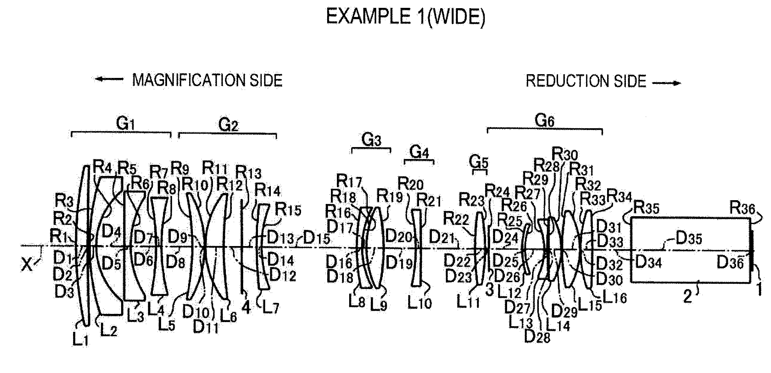
[0051]In this way, it is easy to widen the angle of view of the zoom lens while maintaining a high zoom ratio, and it is possible to maintain the Fno. to be substantially constant in the entire power variation range at a wide angle of view. In addition, since all lenses are single lenses, the zoom lens is suitable as a cinema projection zoom lens that transmits a large quantity of light and is used at a high temperature. Since the aperture diaphragm is arranged closest to the magnification side in the sixth lens group that is fixed when power varies and a moving group is arranged closer to the magnification side than the aperture diaphragm, it is possible to reduce the outside diameter of the lens arranged on the reduction side. Therefore, it is possible to attach the zoom lens to the existing projection display device in which the space for arranging the lens is limited.
[0053]Since the back focal length of the entire system is set as described above, it is possible to ensure a sufficient space to insert a glass block serving as a color composition unit, such as a cross dichroic prism or a TIR prism. In addition, it is possible to meet the demand for high telecentricity on the reduction side of the lens system.

Problems solved by technology

It is inefficient to prepare the individual lenses corresponding to various throw ratios in terms of costs.
Therefore, the lens is not suitable for the movie theater.
However, since the lens disclosed in JP-A-2002-122782 is a varifocal lens, telecentricity is not maintained to be constant when power varies, or after the lens is provided, the adjustment of an operation is complicated when power needs to vary.
Therefore, when the zoom lens is provided in a projection projector apparatus using a light source, such as a xenon lamp that emits light with very high intensity, an adhesive for bonding lenses is significantly altered and deteriorated by the high-intensity light, which causes a reduction in the performance of the lens.

Method used


Image

  • Projection zoom lens and projection display device
  • Projection zoom lens and projection display device
  • Projection zoom lens and projection display device

Examples


example 1

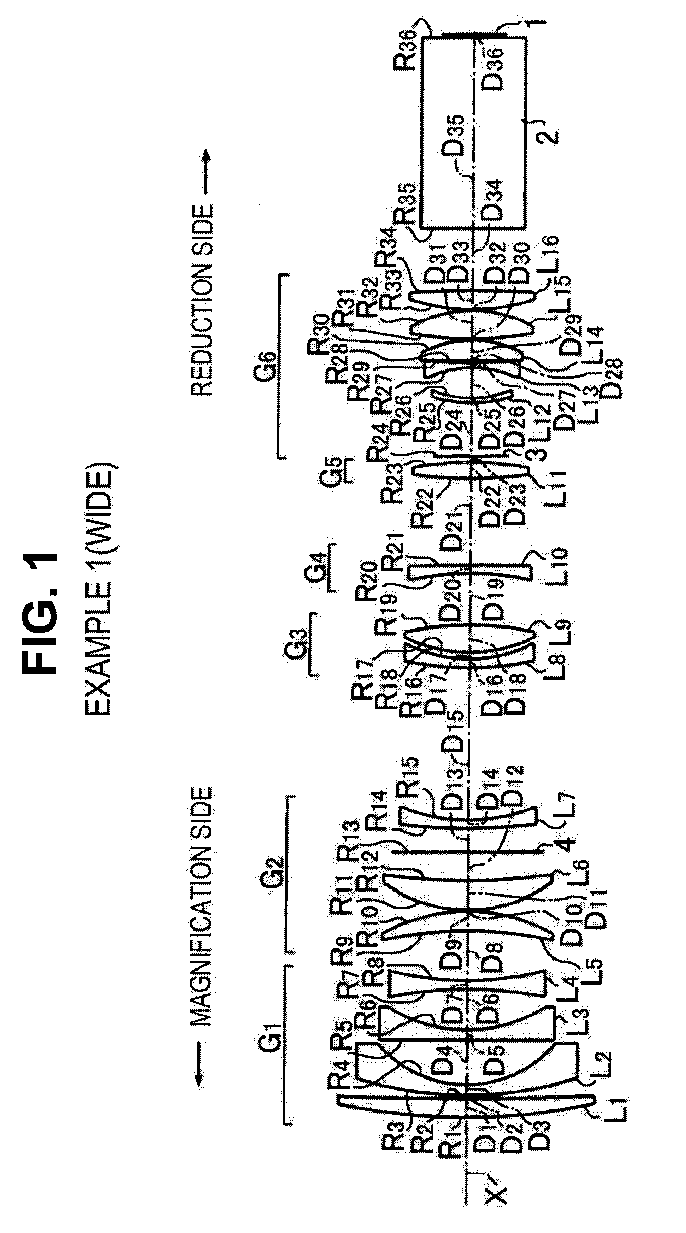
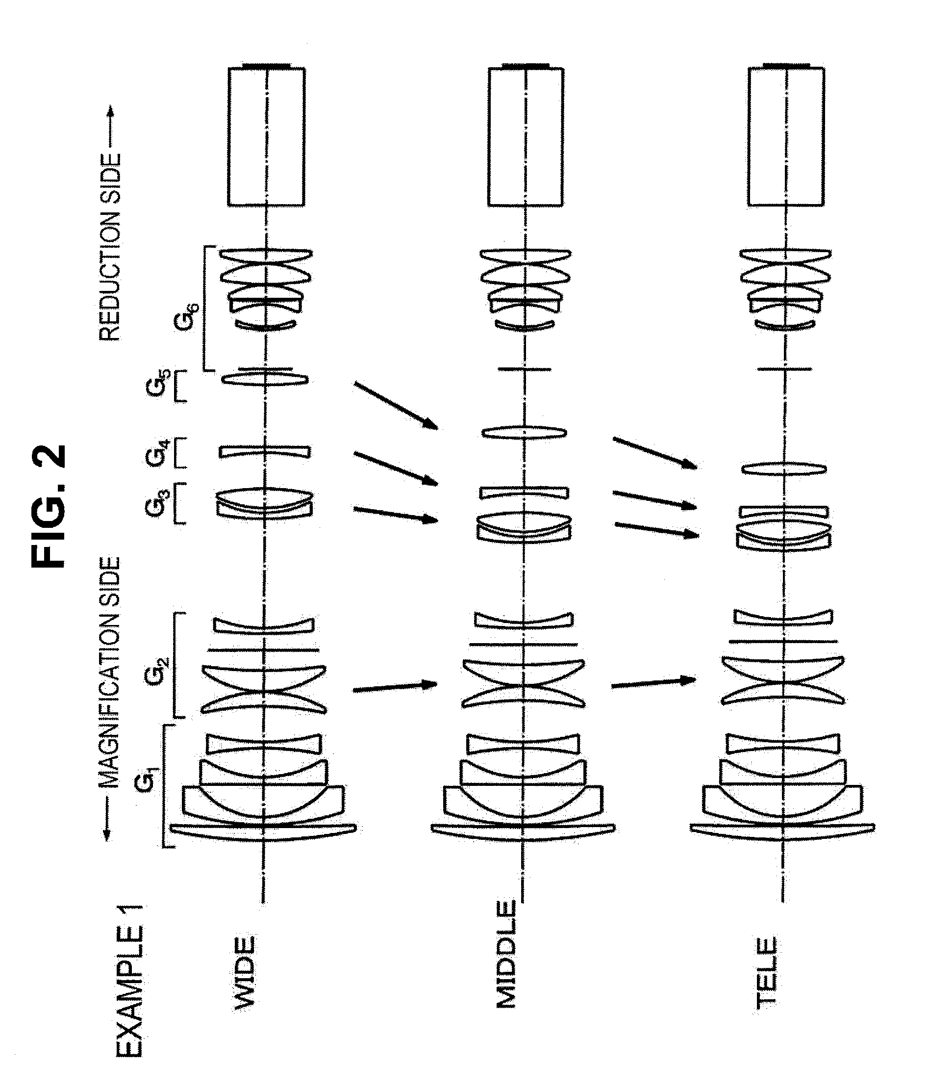
[0117]As described above, the projection zoom lens according to Example 1 shown in FIGS. 1 to 3 includes: a first lens group G1 that is fixed when power varies, has a focusing function, and has a negative refractive power; a second lens group G2 with a positive refractive power, a third lens group G3 with a positive refractive power, a fourth lens group G4 with a negative refractive power, and a fifth lens group G5 with a positive refractive power that are moved in the direction of the optical axis X relative to each other in order to continuously vary power and correct the movement of an image surface due to the continuous power variation; and a sixth lens group G6 that is fixed when power varies, has a positive refractive power, and includes an aperture diaphragm 3 provided closest to the magnification side. The first to sixth lens groups are arranged in this order from the magnification side. A glass block 2, which is mainly a color composition prism, and an image display surface...

example 2

[0131]As shown in FIG. 4, the basic structure of a projection zoom lens according to Example 2 is similar to that according to Example 1 except that the tenth lens L10 in the fourth lens group G4 is a biconcave lens and the thirteenth lens L13 in the sixth lens group G6 is a planoconcave lens having a concave surface facing the magnification side, and the fourteenth lens L14 in the sixth lens group G6 is a positive meniscus lens having a concave surface facing the magnification side.

[0132]As shown in FIG. 5, when power varies, the first lens group G1 and the sixth lens group G6 are fixed and the second to fifth lens groups G2 to G5 are moved.

[0133]In Table 2, an upper part shows the focal length f of the entire system from the wide angle end to the telephoto end in Example 2, the back focal length Bf (air equivalent distance), and Fno.

[0134]In Table 2, a middle part shows the curvature radius R of each lens surface, the thickness of the center of each lens and the air space D betwee...

example 3

[0139]As shown in FIG. 6, the basic structure of a projection zoom lens according to Example 3 is similar to that according to Example 1.

[0140]As shown in FIG. 7, when power varies, the first lens group G1 and the sixth lens group G6 are fixed, and the second to fifth lens groups G2 to G5 are moved.

[0141]In Table 3, an upper part shows the focal length f of the entire system from the wide angle end to the telephoto end in Example 3, the back focal length Bf (air equivalent distance), and Fno.

[0142]In Table 3, a middle part shows the curvature radius R of each lens surface, the thickness of the center of each lens and the air space D between the lenses, and the refractive index Nd and the Abbe number νd of each lens with respect to the d-line.

[0143]In Table 3, a lower part shows the distance D8 (variable 1) between the first lens group G1 and the second lens group G2, the distance D15 (variable 2) between the second lens group G2 and the third lens group G3, the distance D19 (variabl...


PUM


Abstract

A projection zoom lens includes: a first lens group that has a negative refractive power, is fixed when power varies, and has a focusing function; a second positive lens group; a third positive lens group; a fourth negative lens group; a fifth positive lens group; and a sixth lens group that has a positive refractive power, is fixed when power varies, and includes an aperture diaphragm arranged closest to a magnification side. The first to sixth lens groups are arranged in this order from the magnification side, and the second to fifth lens groups are moved when power varies. All lenses are single lenses. The ratio of the back focal length Bf of the entire system to the focal length f of the entire system at a wide angle end is more than 2.5. The Fno. is constant in the entire power variation range.

Description

CROSS-REFERENCE TO RELATED APPLICATIONS[0001]This application is based upon and claims the benefit of priority from the Japanese Patent Application No. 2009-165976 filed on 14 Jul. 2009; the entire contents of which are incorporated herein by reference.BACKGROUND OF THE INVENTION[0002]1. Field of the Invention[0003]The present invention relates to a projection zoom lens which is provided in, for example, a projection display device and includes six lens groups, four of which are moved, and a projection display device including the projection zoom lens, and more particularly, to a projection zoom lens and a projection display device that are suitable to project an image onto a large screen in, for example, a movie theater.[0004]2. Description of the Related Art[0005]In recent years, projectors (projection display devices) that use light valves, such as liquid crystal display devices or DMD display devices, and have a relatively large back focal length have come into widespread use (s...

Claims


Application Information

Patent Timeline
Patent Type & Authority Applications(United States)
IPC IPC(8): G02B15/177G03B21/14
CPCG02B15/177G03B33/12G03B21/14G03B21/142G02B15/1465
Inventor NAGAHARA, AKIKO
Owner FUJIFILM CORP
Learn More