Lighting system

a technology of lighting system and light source, applied in the direction of lighting support device, fixed installation, lighting and heating apparatus, etc., can solve problems such as unattractive atmosphere in the room

Inactive Publication Date: 2011-01-20
KONINKLIJKE PHILIPS ELECTRONICS NV
View PDF10 Cites 16 Cited by
  • Summary
  • Abstract
  • Description
  • Claims
  • Application Information

AI Technical Summary

Benefits of technology

[0004]It is an object of the present invention to provide back side lighting in a LED-based lighting system that alleviates at least one of the above-mentioned drawbacks of the prior art.

Problems solved by technology

However, when providing pendent lights shadowing effects may cause an unattractive atmosphere in the room.

Method used


Image

  • Lighting system
  • Lighting system
  • Lighting system

Examples


Embodiment Construction

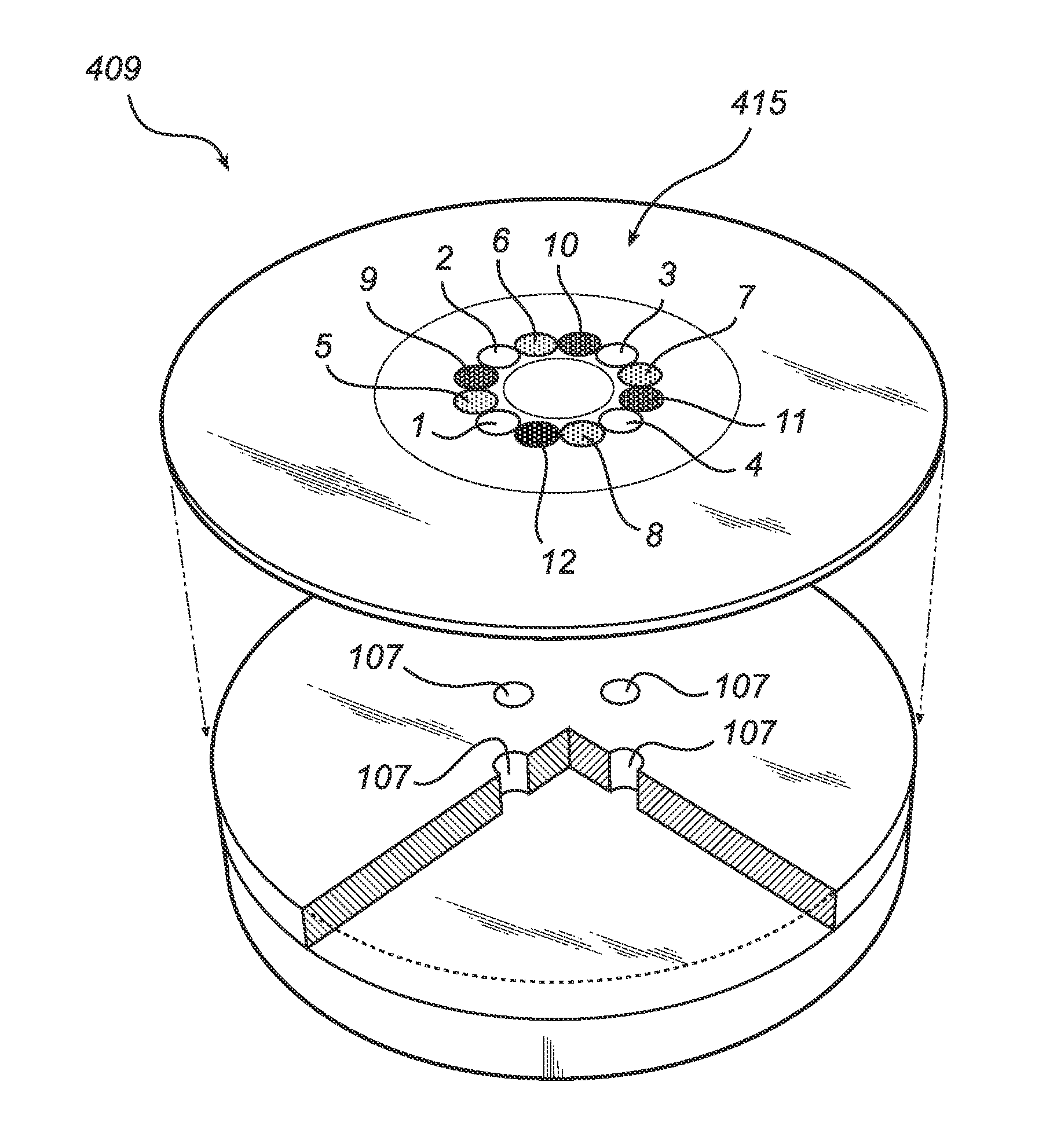
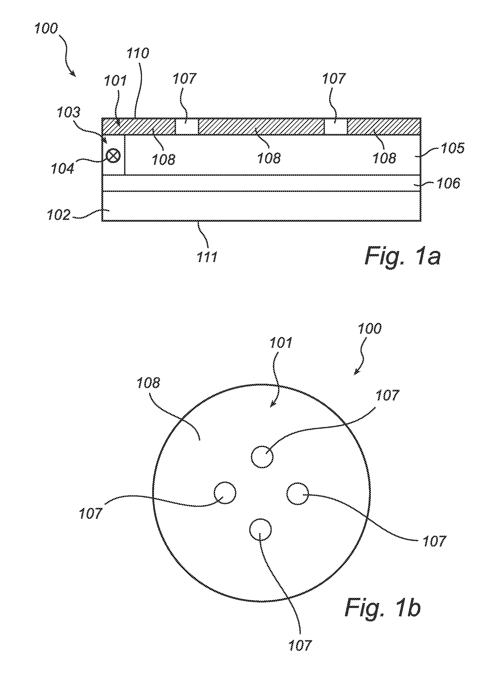
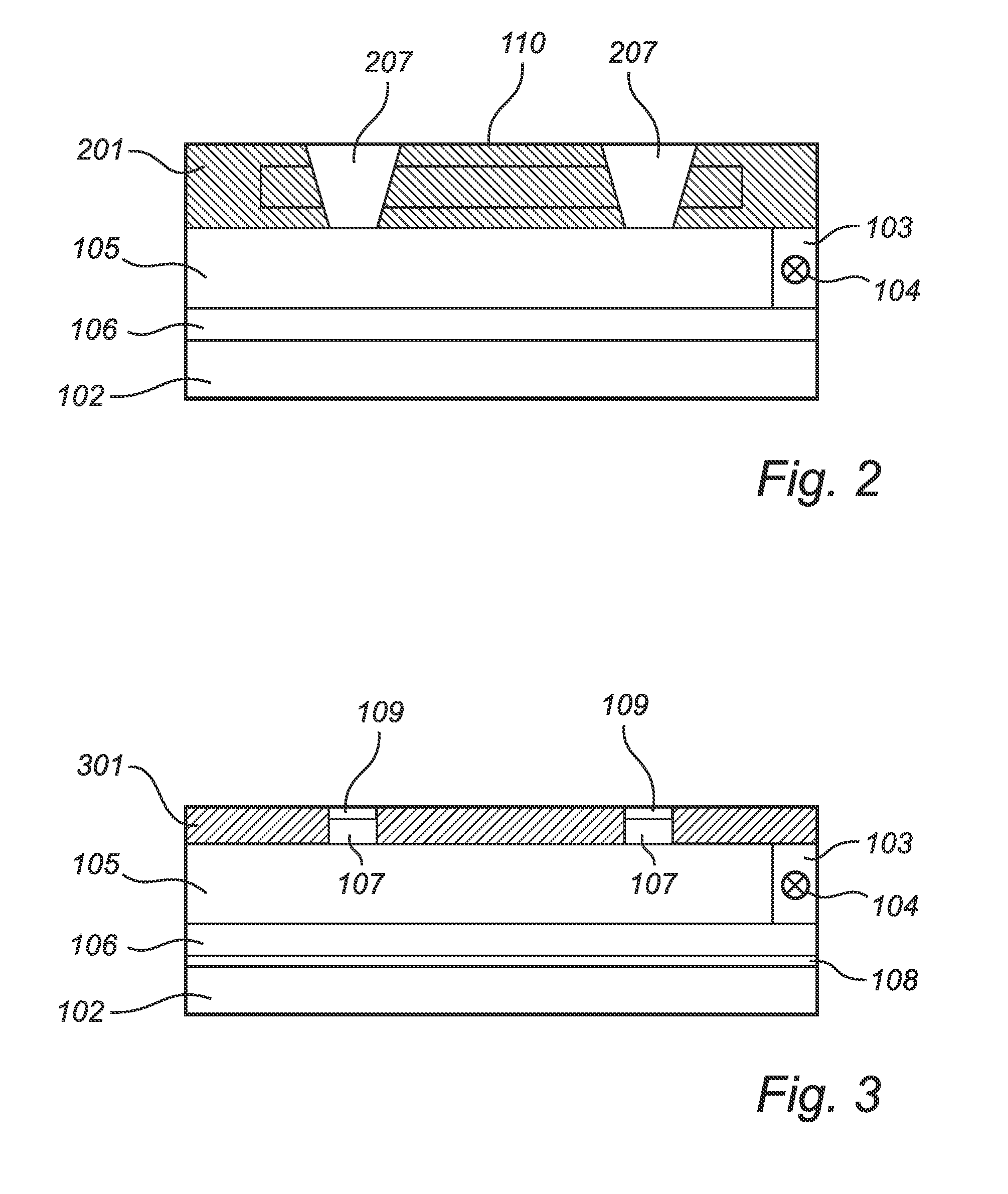
[0043]FIG. 1 illustrates the principle design of a lighting system 100 according to an embodiment of the present invention. The lighting system 100 has a front side 111 and a back side 110. The front side 111 is defined as the side from which the main portion of the light from the lighting system 100 is outputted. This is referred to as the front side lighting. The back side 110 is defined as the side from which back side lighting of the lighting system 100 occurs. The front side 111 and the back side 110 are in this embodiment positioned on opposite sides of the lighting system 100. This is appropriate when the lighting system 100 is arranged in a ceiling and the front side lighting has the purpose of illuminating a room or a working station etc., and the back side lighting has the purpose of reducing shadowing effects that occur or has the purpose of providing atmospheric light directed to the back, e.g. the ceiling, when a lighting system is pendent from a surface.

[0044]The main ...


PUM


Abstract

This invention relates to a lighting system (100) which provides front side lighting, where a main portion of the light is outputted in the front direction of the lighting system, and back side lighting, where a sub portion of the light is outputted in a back side direction of the lighting system. The lighting system is arranged such that light from a light unit (103) is mixed in a mixing chamber (105). The mixing chamber has a first light exit portion (106) which is arranged for outputting a main portion of the mixed light for front side lighting. The mixing chamber is further arranged with a second light exit portion (101) arranged in association with the mixing chamber for outputting a sub portion of the mixed light for back side lighting from the lighting system. The invention is based on an insight that by utilizing the mixing chamber in the lighting system, back side lighting is achieved and thereby hardly affecting the beam shape of the front side lighting from the lighting system.

Description

FIELD OF THE INVENTION[0001]The present invention relates generally to lighting systems and more particularly to a lighting system with backside lighting and a corresponding method for providing back side lighting.BACKGROUND OF THE INVENTION[0002]Lighting systems used for lighting of buildings have previously typically been provided with fluorescent light sources. It is however expected that light emitting diode (LED) based lighting systems will increasingly replace fluorescent light source based lighting systems within the next coming years. Due to their characteristics, such as low power consumption, color generating capabilities, low working temperature, small size etc., LEDs are suitable to use in thin, flat surfaced lighting systems, which are much flatter and more compact than conventional lighting systems, such as an example the Philips MASTER Line 111 Halogen lamp. Thus, LED-based lighting systems provide good conditions to integrate the lighting in the interior of a room or...

Claims


Application Information

Patent Timeline
Patent Type & Authority Applications(United States)
IPC IPC(8): F21V9/00F21S4/00F21V11/00F21V7/00F21Y101/00
CPCF21S8/04F21V7/0008F21Y2101/02F21V11/08F21V7/0016F21Y2115/10
Inventor WILLEMSEN, OSCAR HENDRIKUSIJZERMAN, WILLEM LUBERTUS
Owner KONINKLIJKE PHILIPS ELECTRONICS NV
Why Eureka
Try Eureka