
Light Feature

a technology of light feature and light source, which is applied in the direction of lighting and heating apparatus, semiconductor devices for light sources, and support devices for lighting and heating, etc. it can solve the problems of reduced brightness of led lamps, increased energy consumption of led lamps, and increased heat dissipation of high-power leds. , to achieve the effect of enhancing cooling efficiency and decreasing cross-sectional area

Inactive Publication Date: 2011-01-20
EYE LIGHTING INT OF NORTH AMERICA
View PDF42 Cites 28 Cited by
  • Summary
  • Abstract
  • Description
  • Claims
  • Application Information

AI Technical Summary

Benefits of technology

[0008]The present disclosure provides a lighting apparatus having more efficient heat dissipation.
[0020]The lighting apparatus may further include a mounting apparatus that facilitates physically coupling the lighting apparatus to a fixture.
[0021]The lighting apparatus may further include a guard piece that prevents the light emitted by the light source module from shining toward at least one direction.
[0034]Thus, with the proposed design, heat is transferred from the light source to the heat dissipation module via vertical heat transfer as opposed to horizontal heat transfer. Additionally, the heat dissipation fins form air channels that have a decreasing cross-sectional areal as air rises up the air channels. With at least one of the fins curved in shape, the heat-absorbing air is compressed as it rises up the air channels. This causes a spiral effect, or turbulence, in the air to result in enhanced efficiency in cooling.

Problems solved by technology

More specifically, electrons and holes in the semiconductor material are combined to release excessive energy in the form of light when a current is applied to the semiconductor material.
Generally speaking, high-power LEDs tend to encounter a heat dissipation problem.
When an LED is operated at an overly high temperature, the brightness of the LED lamp may be reduced and the lifespan of the LED may be shortened.

Method used


Image

  • Light Feature
  • Light Feature
  • Light Feature

Examples


Embodiment Construction

[0067]Reference will now be made in detail to the present preferred embodiments of the present disclosure, examples of which are illustrated in the accompanying drawings. Wherever possible, the same reference numbers are used in the drawings and the description to refer to the same or like parts.

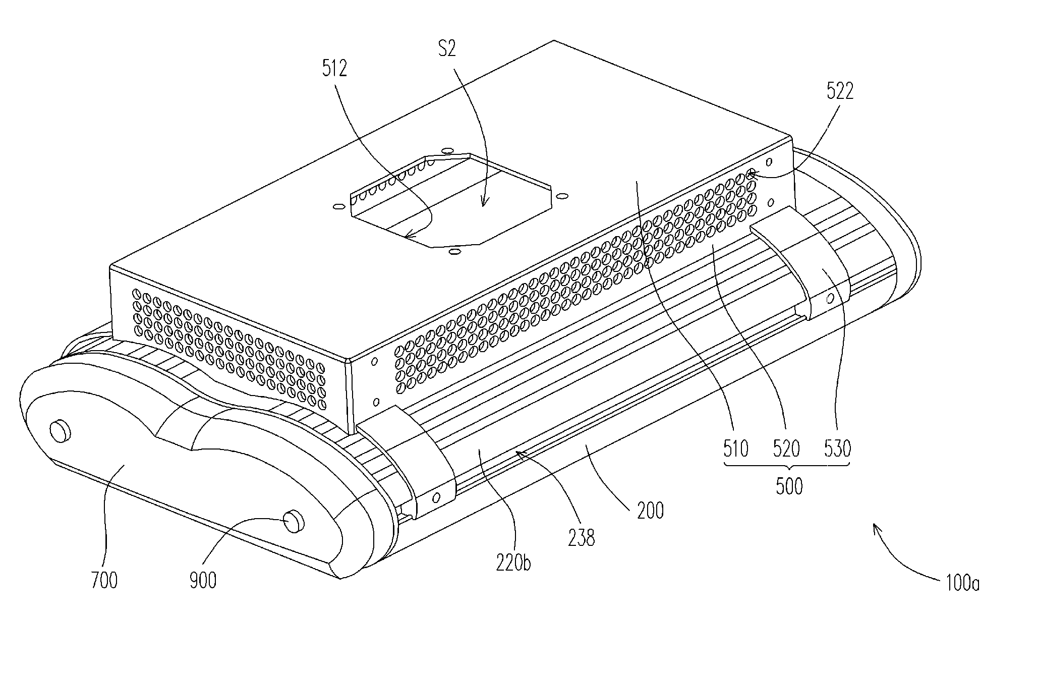
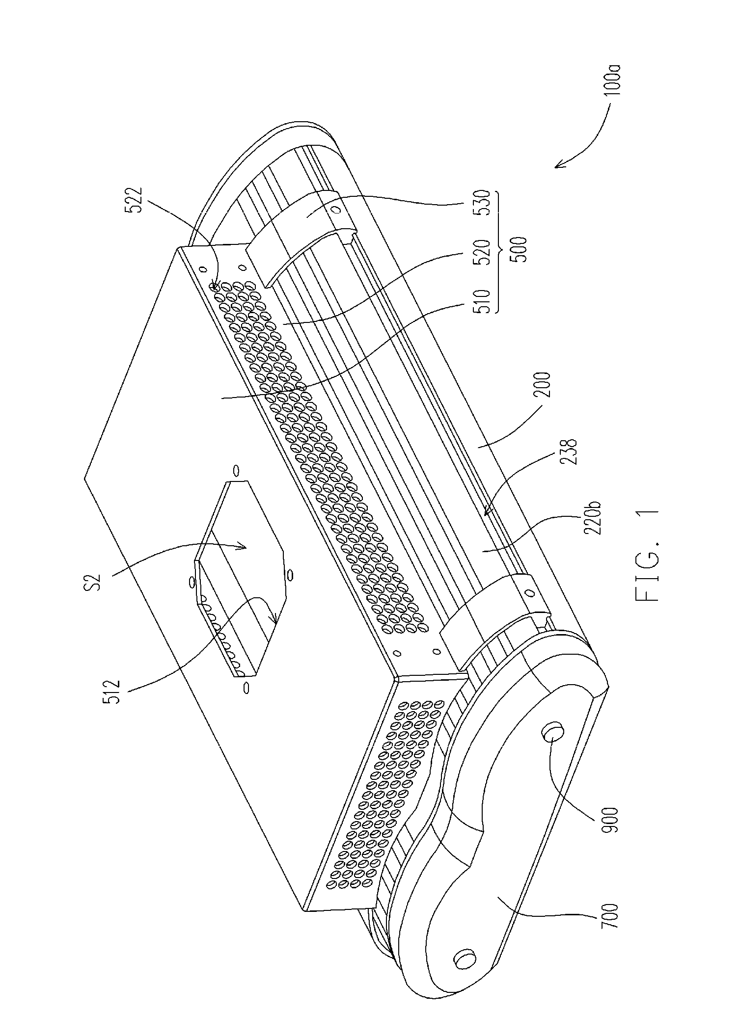
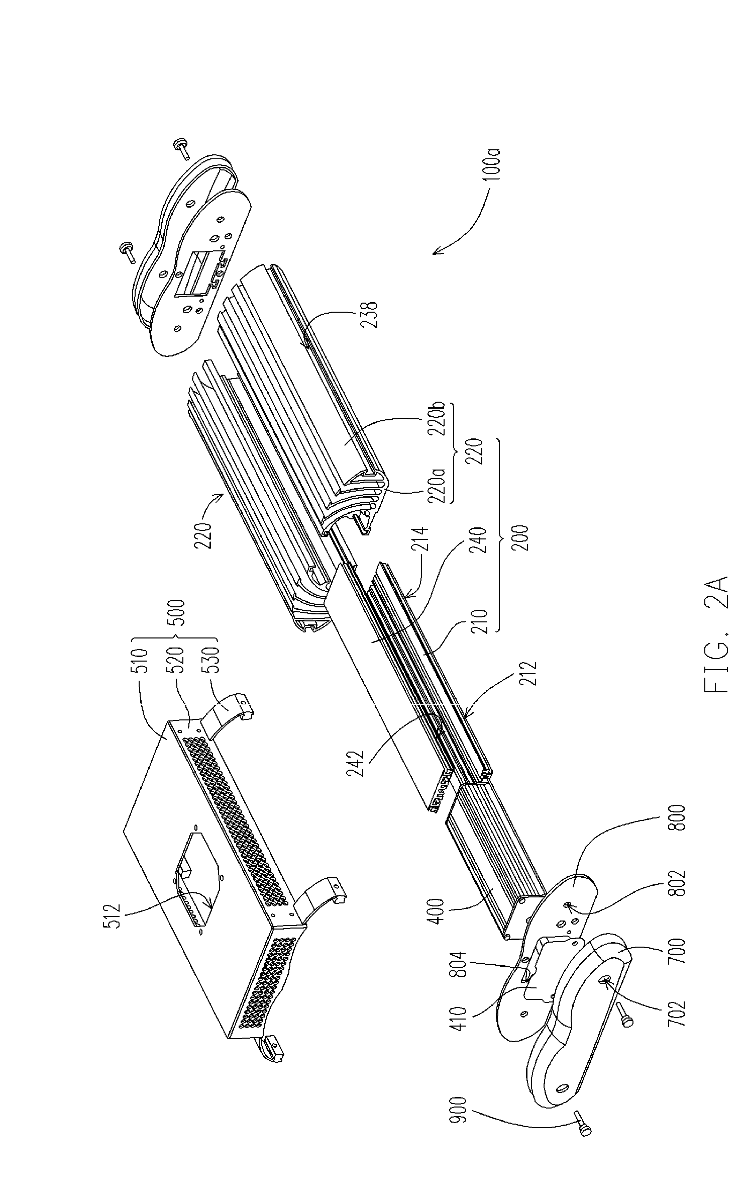
[0068]FIG. 1 is a schematic perspective view of a lighting apparatus according to one embodiment of the present disclosure; FIG. 2A is a schematic exploded view of the lighting apparatus in FIG. 1; FIG. 2B is a partially enlarged view of the heat sink of the lighting apparatus in FIG. 2A; FIG. 2C is a partially enlarged view of the first connection element of the lighting apparatus in FIG. 2A; FIG. 2D is a schematic perspective view of the heat dissipation module of the lighting apparatus in FIG. 2A. Referring to FIG. 1 and FIG. 2B at first, in this embodiment, a lighting apparatus 100a including a heat dissipation module 200 and a light-emitting diode (LED) module 300 is provided.

[0069]To b...


PUM


Abstract

A lighting apparatus includes a light source module and a heat dissipation module. The light source module emits light and generates heat. The heat dissipation module dissipates at least a portion of the heat, and includes a base portion to which the light source module is physically coupled. The heat dissipation module also includes a plurality of heat dissipation fins. At least two of the fins that are immediately adjacent to one another form an air channel having a first opening and a second opening between the at least two of the fins. The air channel has a generally decreasing cross-sectional area with respect to air rising up the air channel in a generally vertical direction with respect to a horizontal plane as the air enters the air channel through the first opening and exits the air channel through the second opening.

Description

CROSS-REFERENCE TO RELATED APPLICATION[0001]This application is a continuation-in-part application and claims the priority benefit of U.S. non-provisional application Ser. No. 12 / 752,105, filed on Mar. 31, 2010, which claims the priority benefit of U.S. provisional application Ser. No. 61 / 225,712, filed on Jul. 15, 2009. The entirety of the above-mentioned patent applications are hereby incorporated by reference herein and made a part of this specification.BACKGROUND[0002]1. Technical Field[0003]The present disclosure generally relates to a lighting apparatus, and in particular, to a lighting apparatus having more efficient heat dissipation.[0004]2. Description of Related Art[0005]A light-emitting diode (LED) is a semiconductor device that is fabricated by using a compound of chemical elements selected from the groups III-V, such as GaP, GaAs, and so forth. This kind of semiconductor material has the property of converting electrical energy into light. More specifically, electrons a...

Claims


Application Information

Patent Timeline
Patent Type & Authority Applications(United States)
IPC IPC(8): F21V29/00F21V11/00F21V21/00F28F13/00
CPCF21V15/01F21V29/004F21Y2101/02F28D2021/0029F21V29/83F28F13/08F21V29/71F21V29/77F28F3/02F21Y2115/10
Inventor LITTLE, JR., WILLIAM D.
Owner EYE LIGHTING INT OF NORTH AMERICA
Features
  • Generate Ideas
  • Intellectual Property
  • Life Sciences
  • Materials
  • Tech Scout
  • Unparalleled Data Quality
  • Higher Quality Content
  • 60% Fewer Hallucinations
Learn More