Illumination-Improving Structure for LED or SMD LED lights

a technology of led lights and structures, applied in point-like light sources, lighting and heating devices, lighting device details, etc., can solve the problems of poor illumination uniformity, poor light uniformity, and large drops, so as to improve light uniformity and luminance, reduce halation, and regulate the projection angle

Inactive Publication Date: 2011-01-20
HU WEN SUNG
View PDF8 Cites 8 Cited by
  • Summary
  • Abstract
  • Description
  • Claims
  • Application Information

AI Technical Summary

Benefits of technology

[0009]A main objective of the present invention is to provide an illumination-improving structure for LED or SNM LED lights that eliminates halation, improves light uniformity and luminance and regulates projecting angles.

Problems solved by technology

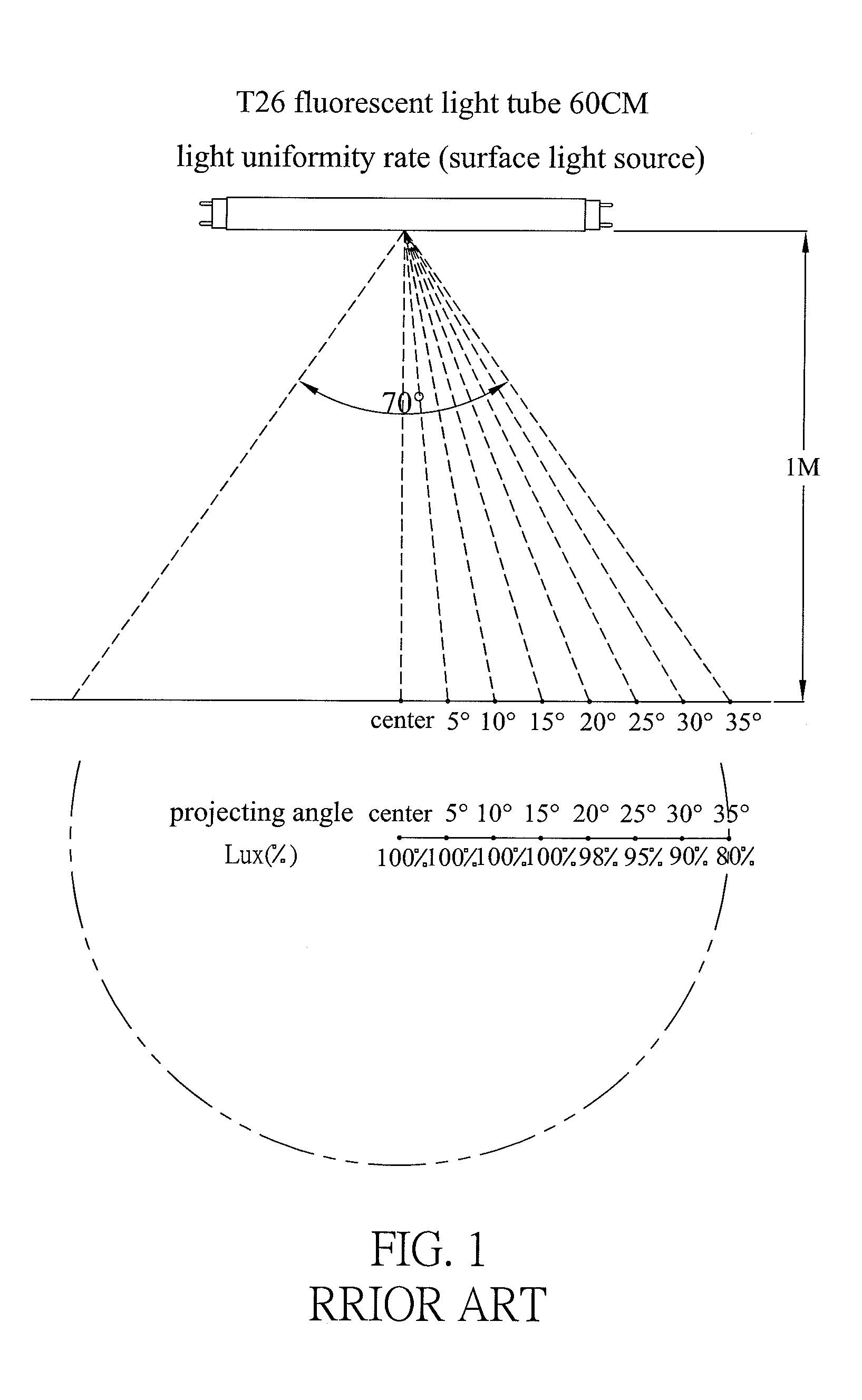
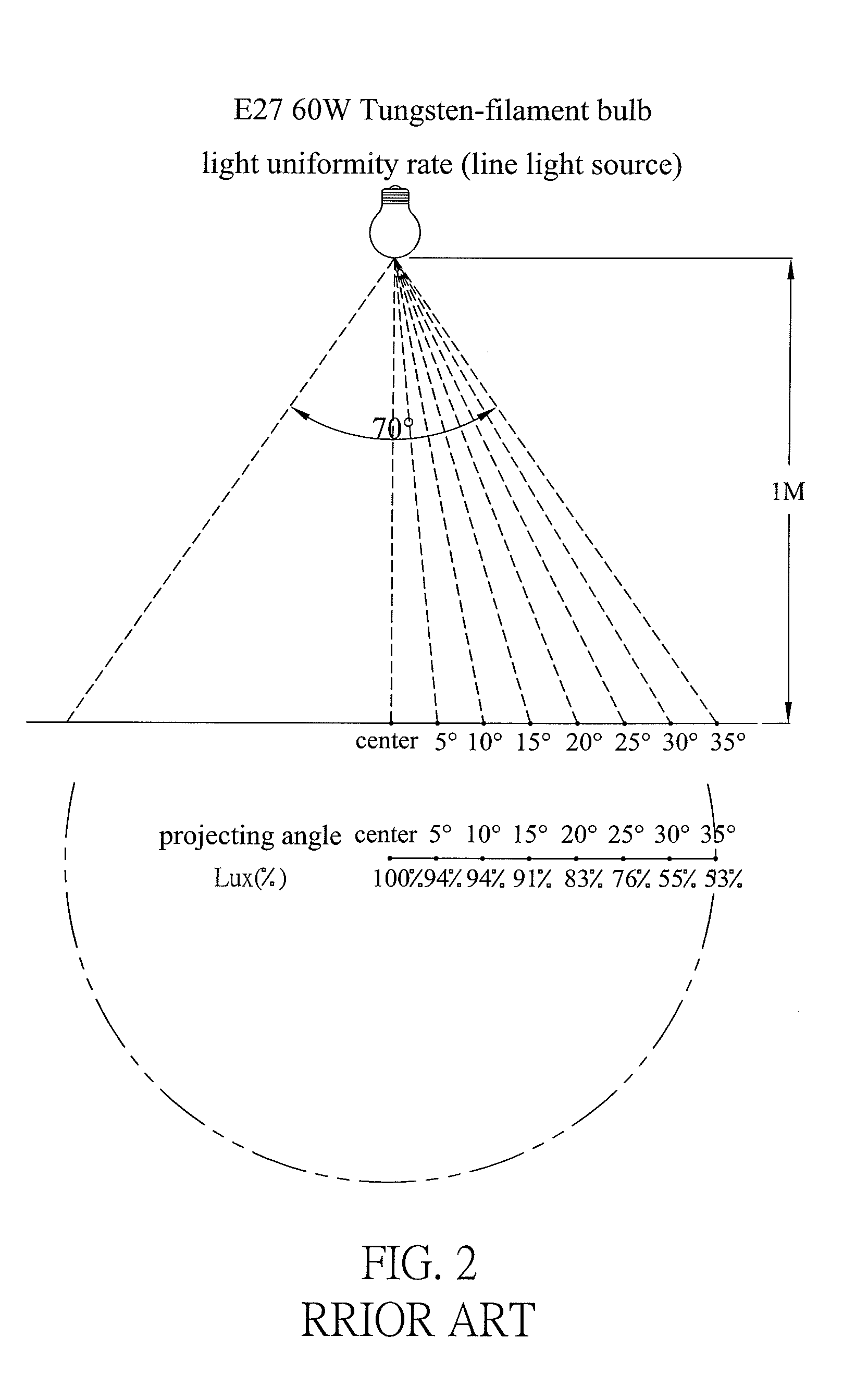
1. The conventional LED bulb is a spot light source and thus usually performs halation phenomenon. Unlike halide bulb and tungsten bulb which are line light sources or high-pressure sodium lamp or fluorescent lamp (such as fluorescent light tube, compact fluorescent lamp), HID bulbs which are activated by sodium, mercury or xenon elements to perform planar light source, the spot light source of LED causes uneven LUX with great drops to the projecting surfaces it projects thereto and has poor illumination uniformity in comparison with the fluorescent light tube, compact fluorescent lamp and tungsten bulb especially serving as reading lights (as shown in FIGS. 1 to 4).
2. The conventional LED illumination lights all embed one or multiple LED units into one or multiple V-shaped recesses in a heat sink base. Although the V-shaped recesses adjust the projecting angles of the light from LED units, wide-angle light is also interrupted and transformed to refraction light. In other words, light from LED spot light source out of direct light range within the V-shaped recess will be refracted by sidewalls therein to cause irregular and uneven fraction light which also damps the uniformity in illumination (as shown in FIGS. 5 and 6).
3. The conventional LED bulbs or lamps with high lumens all need heat sink base to disperse heat, wherein LED lamps having low watts (take 1 W for example) can sufficiently disperse or conduct heat by attaching heat sink base (as shown in FIGS. 5 and 6). However, LED lamps having high watts (for example, 3 W or 5 W) or a small substrate collecting multiple 1 W LED units can not sufficiently disperses the high heat even by attaching the heat sink base made of copper or aluminum boards. Therefore, the conventional LED lamps cannot protect the LED units with chips within the limitation temperature (60 to 65° C.) to decrease their decay and thus to stabilize their lifespan.

Method used


Image

  • Illumination-Improving Structure for LED or SMD LED lights
  • Illumination-Improving Structure for LED or SMD LED lights
  • Illumination-Improving Structure for LED or SMD LED lights

Examples


Embodiment Construction

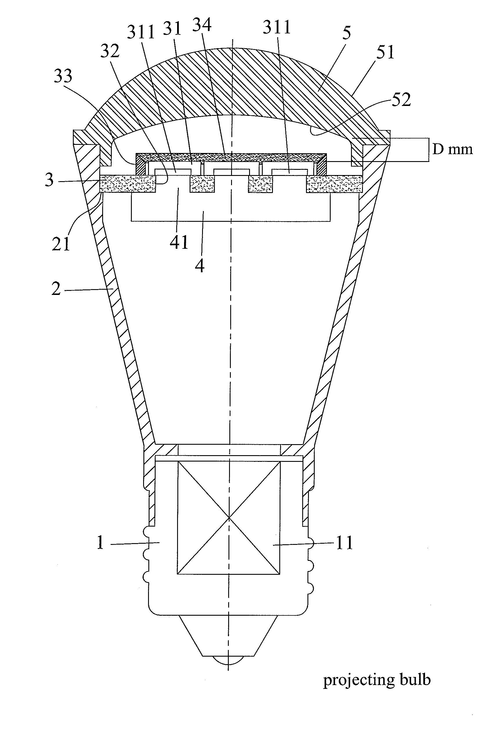
[0045]An illumination-improving structure for LED or SMD LED lights in the present invention is to mount a lamp base at a light head. The lamp base is funnel-shaped and has an interior annular cutout near its top edge. A substrate engages the annular cutout to carry one or multiple LED or SMD LED units at a center or other proper locations. Moreover, a rim is formed on the substrate to surround the LED or SMD LED units. The lamp base further has a light-adjusting lens mounted over the LED or SMD LED units. The light-adjusting lens has an outer convex arc performing a plane with edge surface and has an inner concave arc or an inner planar surface. The plane and the outer convex arc are connected in form of sharp angle attachment. The inner concave arc or the inner planar surface are treated with foggy treatment or coated with foggy paper. By having above features and adjusting distance between the LED or SMD LED units and the light adjusting lens, the illumination-improving structure...


PUM


Abstract

An illumination-improving structure for LED or SMD LED lights is to mount a lamp base at a light head. The lamp base is funnel-shaped and has an interior annular cutout near its top edge. A substrate engages the annular cutout to carry one or multiple LED or SMD LED units at a center or other proper locations. Moreover, a rim is formed on the substrate to surround the LED or SMD LED units. The lamp base further has a light-adjusting lens mounted over the LED or SMD LED units. The light-adjusting lens has an outer convex arc performing a plane with edge surface and has an inner concave arc or an inner planar surface. The plane and the outer convex arc are connected in form of sharp angle attachment. The inner concave arc or the inner planar surface are treated with foggy treatment or coated with foggy paper.

Description

BACKGROUND OF THE INVENTION[0001]1. Field of the Invention[0002]The present invention relates to an illumination-improving structure, and more particularly to an illumination-improving structure that eliminates halation, improves light uniformity and luminance and regulates projecting angles.[0003]2. Description of Related Art[0004]Theoretically, light emitting diode (LED) is a light source has longest lifespan, lowest heat, lowest chemical pollution and electricity consumption so that application of LED is the major trend of present illumination having environmental and energy-saving efficiency.[0005]However, taking LEDs to make a conventional bulb still has some drawbacks as below:[0006]1. The conventional LED bulb is a spot light source and thus usually performs halation phenomenon. Unlike halide bulb and tungsten bulb which are line light sources or high-pressure sodium lamp or fluorescent lamp (such as fluorescent light tube, compact fluorescent lamp), HID bulbs which are activ...

Claims


Application Information

Patent Timeline
Patent Type & Authority Applications(United States)
IPC IPC(8): F21V3/00
CPCF21V5/04F21Y2101/02F21K9/17F21K9/137F21Y2103/003F21K9/233F21K9/27F21Y2103/10F21Y2115/10F21K9/69
Inventor HU, WEN-SUNG
Owner HU WEN SUNG
Why Eureka
Try Eureka