Receiver and method

a receiver and receiver technology, applied in the field of receivers and methods, can solve the problems that the recovery of data from the useful part of the ofdm symbols at the receiver can nevertheless present a technical problem, and achieve the effect of improving the integrity of the receiver, speeding up the identification process, and improving the accuracy of the identification process

Inactive Publication Date: 2011-01-20
SONY CORP
View PDF6 Cites 64 Cited by
  • Summary
  • Abstract
  • Description
  • Claims
  • Application Information

AI Technical Summary

Benefits of technology

[0006]Furthermore, once the OFDM symbol has been transformed into the frequency domain, it is desirable to identify any frequency offsets on the recovered sub-carriers which are greater than the width of a sub-carrier (i.e. inter-sub-carrier offsets) in order that data can be extracted correctly from each sub-carrier, which will improve the integrity of the receiver.
[0007]A receiver arranged in accordance with the present invention provides an advantage in that a number of correlators, each arranged to detect correlations according to a different guard interval length, are run concurrently. Accordingly, there is no requirement to separately identify the guard interval length prior to determine the symbol boundaries which will speed up and improve an accuracy of the process of identifying the OFDM symbol boundaries. Furthermore, a coarse frequency offset detector is provided which determines a coarse frequency offset of the frequency transformed symbols by identifying a pilot sub-carrier pattern in the received symbols. This provides an advantage because a conventional feature of the received symbols (i.e. the pilot sub-carriers arranged in a pilot pattern) is used to determine the coarse frequency offset. This mitigates the requirement to include any further signalling in the OFDM symbols from which to derive the coarse frequency offset and also efficiently re-uses the pilot data which will be typically decoded in any case in order to provide a channel estimate at the receiver.

Problems solved by technology

However, detecting and recovering data from the useful part of the OFDM symbols at the receiver can nevertheless present a technical problem.

Method used


Image

  • Receiver and method
  • Receiver and method
  • Receiver and method

Examples


Embodiment Construction

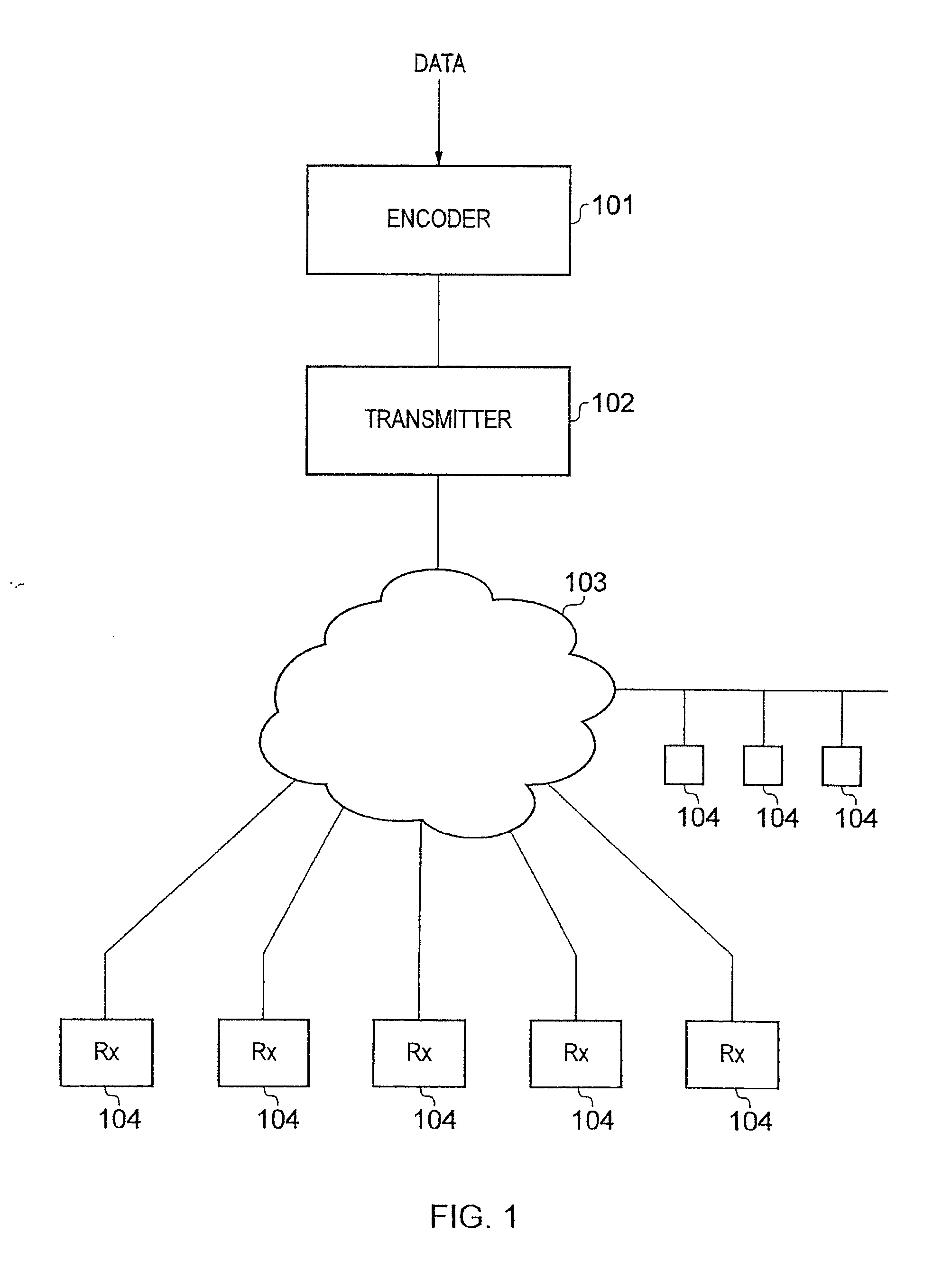
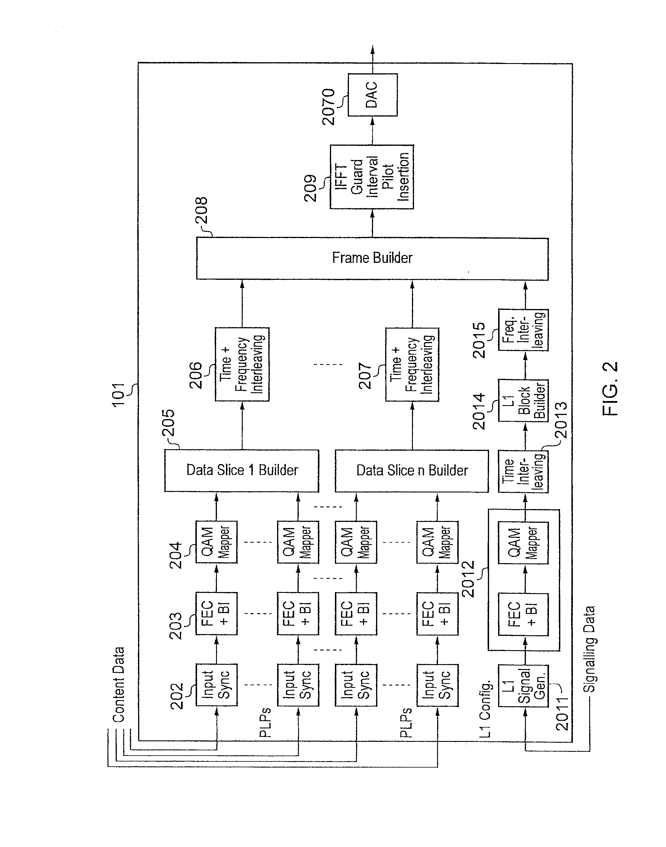
[0030]Example embodiments of the present invention are described in the following paragraphs with reference to a receiver operating in accordance with the DVB-C2 standard, although it will be appreciated that embodiments of the present invention find application with other DVB standards and indeed other communications systems which utilise Orthogonal Frequency Division Multiplex (OFDM).

OFDM Data Transmission

[0031]OFDM systems transmit data simultaneously on a series of orthogonal frequency sub-carriers. The frequency sub-carriers transmitted over a period of time make up a series of OFDM symbols.

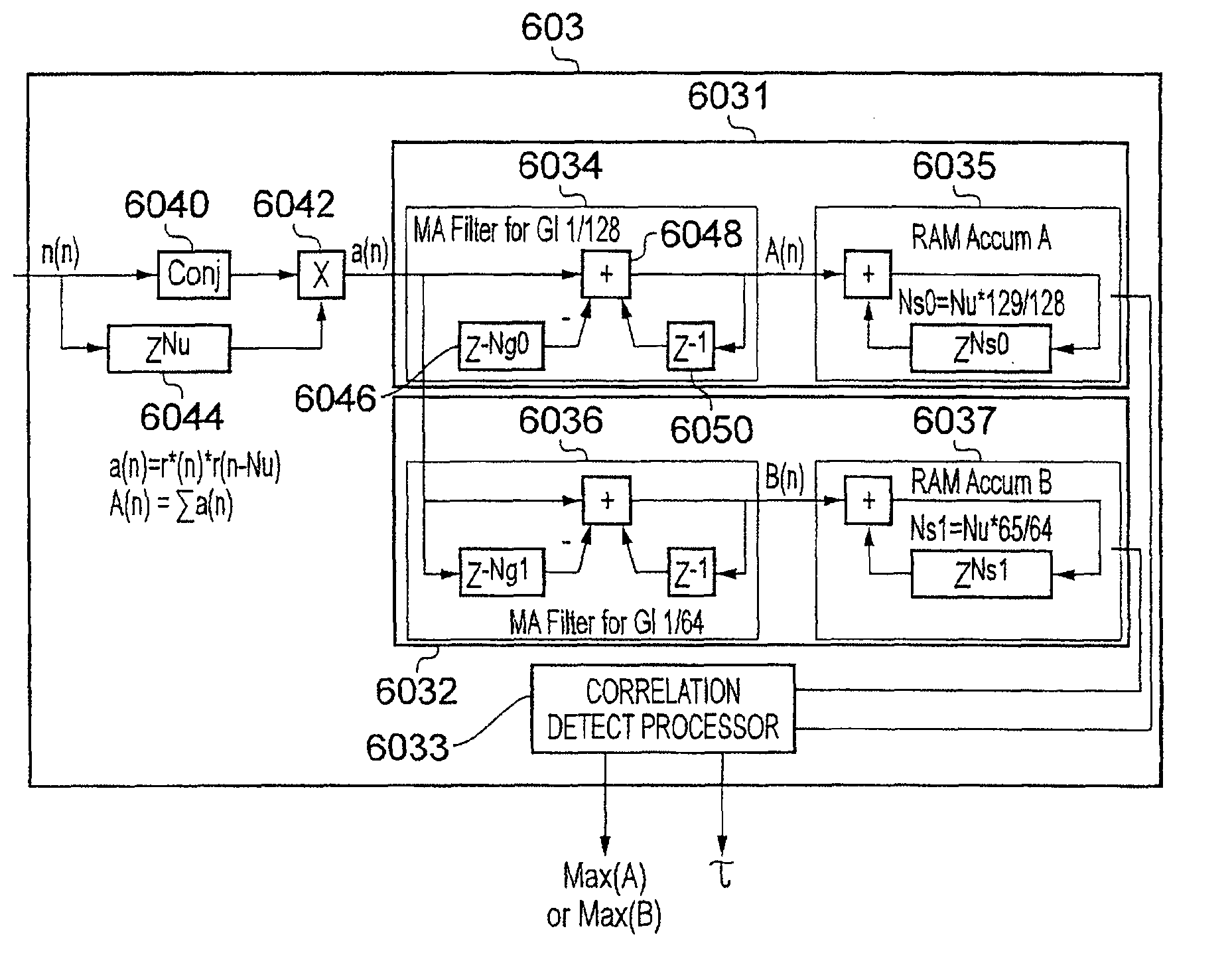
[0032]In order to reduce the effects of multi-path propagation and other effects, each OFDM symbol typically includes a guard interval. A guard interval is a portion of each OFDM symbol in the time domain that is copied from one end of the OFDM symbol and inserted at the other. Therefore the total duration of an OFDM symbol will be T=Tg+Tu, where Tg is the guard interval duration and Tu is t...


PUM


Abstract

A receiver for detecting and recovering data from Orthogonal Frequency Division Multiplexed (OFDM) symbols. The receiver comprises a demodulator, symbol synchronization unit, frequency transform processor, and coarse frequency offset detector. The demodulator generates sampled symbols. The symbol synchronisation unit has correlators, which receives the sampled symbols, and a correlation detection processor. Each correlator auto correlates each sampled symbol, and the correlation detection processor determines a start point of each symbol. The frequency transform processor receives the sampled symbols and performs a frequency transform on each symbol. The coarse frequency offset detector includes a pilot data filter, which includes taps corresponding to a value and spacing of the pilot pattern of the symbols and arranged to receive as an input the frequency domain symbols from the frequency transform processor, and a coarse frequency offset detect processor, which is arranged to detect a coarse frequency offset output from the pilot data filter.

Description

FIELD OF THE INVENTION[0001]The present invention relates to receivers and methods for detecting and recovering data from Orthogonal Frequency Division Multiplexed (OFDM) symbols that have been transmitted via a channel.BACKGROUND OF THE INVENTION[0002]There are many examples of communications systems in which data is communicated using Orthogonal Frequency Division Multiplexing (OFDM). Systems which have been arranged to operate in accordance with Digital Video Broadcasting (DVB) standards for example, utilise OFDM. OFDM can be generally described as providing K narrow band sub-carriers (where K is an integer) which are modulated in parallel, each sub-carrier communicating a modulated data symbol such as Quadrature Amplitude Modulated (QAM) symbol or Quadrature Phase-shift Keying (QPSK) symbol. The modulation of the sub-carriers is formed in the frequency domain and transformed into the time domain for transmission. The sub-carriers are modulated in parallel contemporaneously, so t...

Claims


Application Information

Patent Timeline
Patent Type & Authority Applications(United States)
IPC IPC(8): H04L27/06
CPCH04L27/2656H04L27/2659H04L27/2678H04L27/2662H04L27/2675H04L27/266H04L27/2647H04L27/2649
Inventor ATUNGSIRI, SAMUEL ASANGBENG
Owner SONY CORP
Why Eureka
Try Eureka