System of counter-rotating propellers with a feathering device for propeller blades

a technology of propeller blades and feathering devices, which is applied in the direction of rotors, marine propulsion, vessel construction, etc., can solve the problem of no longer being able to feather, and achieve the effect of reducing the shock produced by encounters

Active Publication Date: 2011-01-20
SN DETUDE & DE CONSTR DE MOTEURS DAVIATION S N E C M A
View PDF5 Cites 25 Cited by
  • Summary
  • Abstract
  • Description
  • Claims
  • Application Information

AI Technical Summary

Benefits of technology

[0017]It should be noted that the second case indicated above is differentiated from the first case in the sense that the feathering of the blades of the propeller, which sees the rotating means of actuating thereof rotate in a direction opposite to the direction of the associated rotor, takes place more rapidly than the feathering of the blades of the blades of the other propeller which sees the rotating means of actuating thereof rotating in the same direction as the direction of the associated rotor, but with a lower speed because of the deceleration driven by the other blade, via the means of disengaging.
[0018]Moreover, it is indicated that the system of counter-rotating propellers is preferably designed so that when the sliding elements arrive at the end of travel in the translation movement thereof with respect to the associated rotating means of actuating, positioning the blades of same in the neutral position, the stops established at the end of travel prevent same from continuing to slide along the rotating means of actuating, despite the application of the differential speed of rotation between these elements. Thus, this generates a blockage, leading the sliding elements to be become rigidly fixed in rotation to the associated rotating means of actuating. For information only, it is noted that these stops can be flexible, so as to minimize the shocks produced by the encounters between the sliding elements and the associated stops.

Problems solved by technology

However, in the case of failure of the control systems for stalling the blades, feathering is no longer possible, which is naturally unacceptable.

Method used


Image

  • System of counter-rotating propellers with a feathering device for propeller blades
  • System of counter-rotating propellers with a feathering device for propeller blades
  • System of counter-rotating propellers with a feathering device for propeller blades

Examples


Embodiment Construction

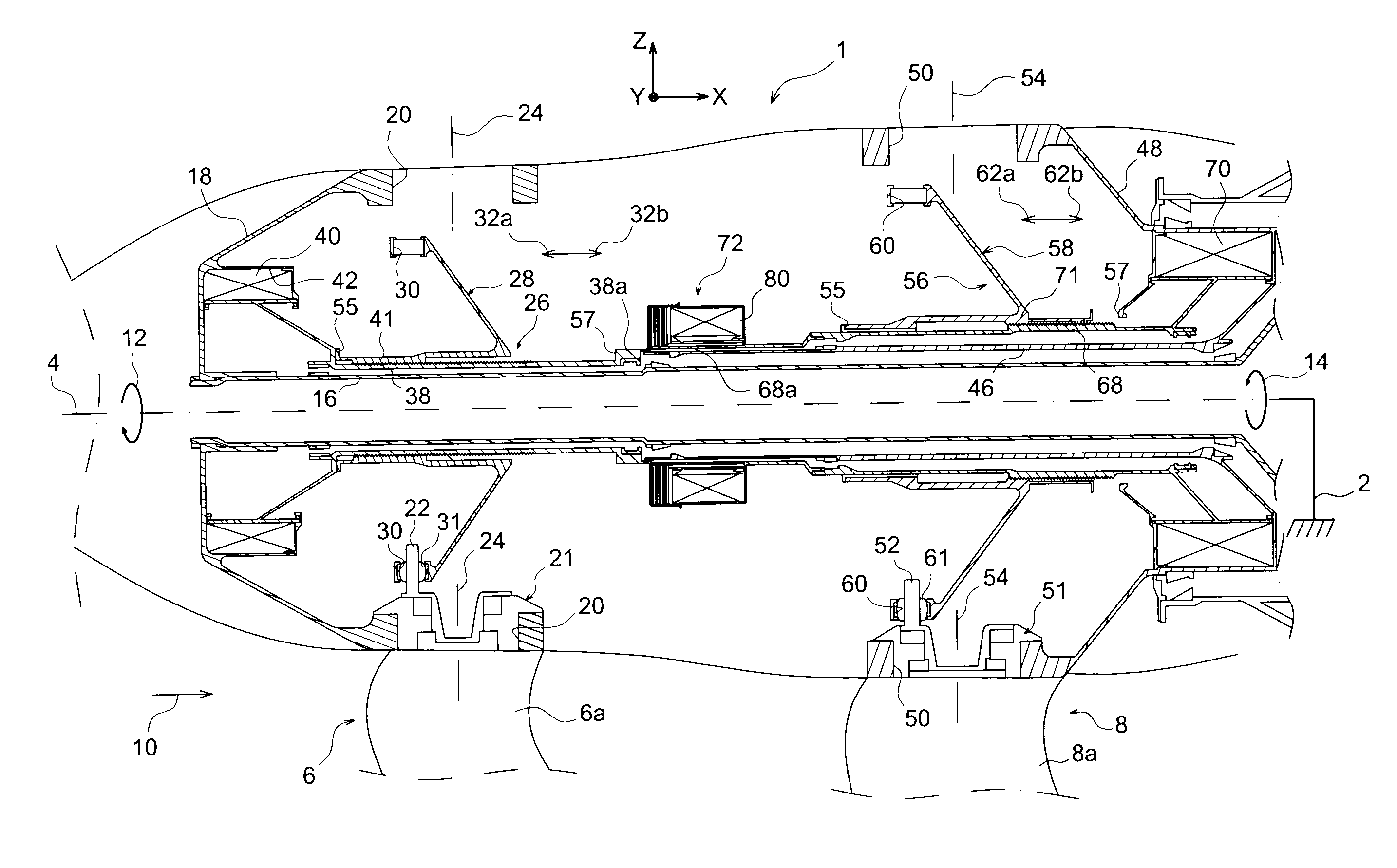
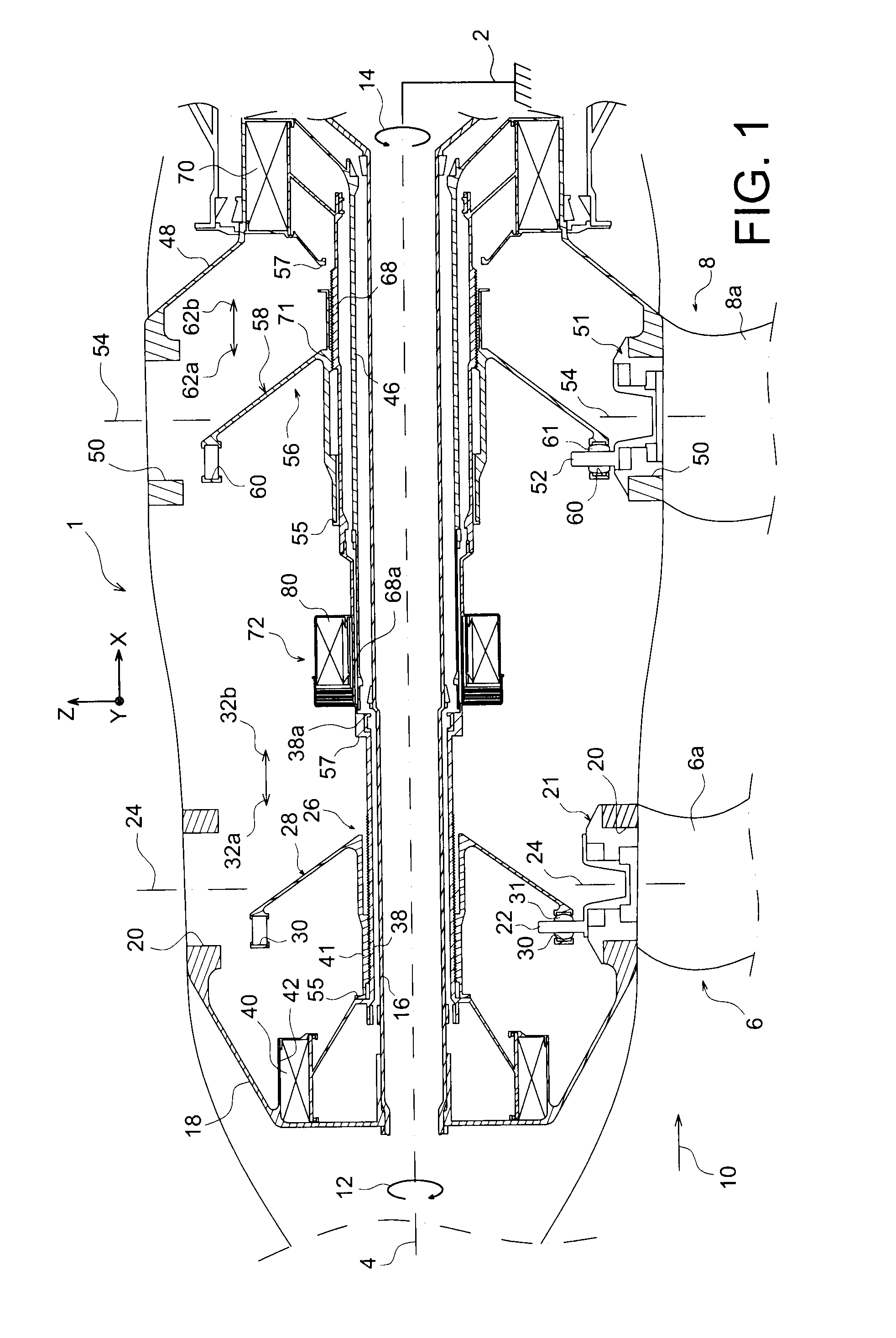
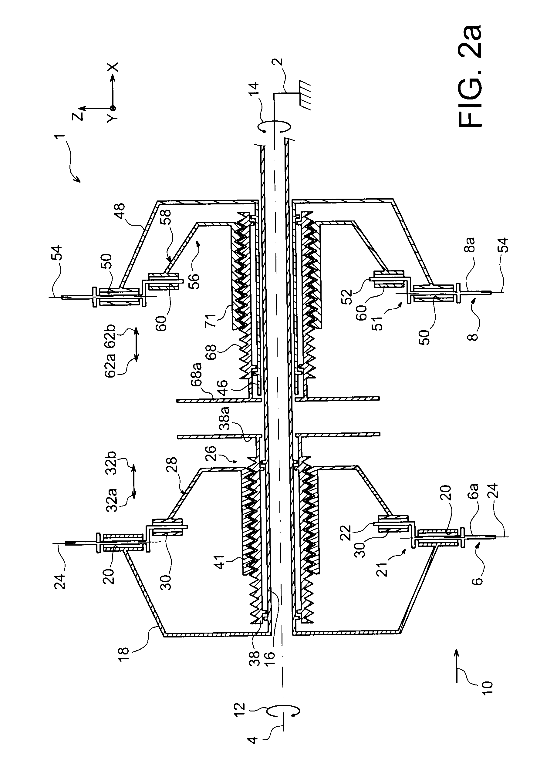
[0033]With reference to FIG. 1, a part of the system of counter-rotating propellers 1 for an aircraft turbine engine can be seen, according to a preferred embodiment of the present invention.

[0034]The X axis corresponds to the longitudinal direction of the propeller system 1, a direction which also corresponds to the longitudinal direction of the turbine engine intended to integrate such a propeller system 1. The Y axis corresponds to the transverse direction of the propeller system 1, and the Z axis to the vertical direction or to the height, these three axes being mutually orthogonal.

[0035]The propeller system 1 comprises a stator or a casing 2 (only schematically shown), centered on a longitudinal axis 4 of the system, parallel to the X axis. This stator is intended to be rigidly attached in a known way to the other casings of the turbine engine. In this respect, it is indicated that the propeller system 1 is preferably designed so that the propellers lack an external radial shro...


PUM


Abstract

A system of counter-rotating propellers for an aircraft turbine engine including a first and a second propeller, each including a stalling control system for the blades, a rotating actuating mechanism for sliding an element to move the angle of attack of the blades, and a disengaging mechanism for rigidly fixing in rotation the rotating actuating mechanism. The system is designed so that when the disengaging mechanism is engaged, a relative rotation speed is created between the elements and the associated rotating actuating mechanism thereof, bringing the blades into a neutral position thereof for feathering.

Description

TECHNICAL FIELD[0001]The present invention relates, in a general way, to a system of counter-rotating propellers for turbine engine aircraft, and more particularly to a system of counter-rotating propellers with means of allowing the feathering of the blades of the two propellers.[0002]The invention also relates to an aircraft turbine engine, comprising such a system of counter-rotating propellers.PRIOR ART[0003]In the prior art, turbine engines with a counter-rotating propeller system are known where the propellers are driven by rotors turning respectively in opposite directions of rotation. These propeller systems are generally designed to allow the feathering of the propeller blades, i.e. for stalling same so that they present the smallest possible angle of attack with respect to the axis of the associated turbine engine. In such a case, we talk about a position of minimum angle of attack, of a minimum angle position or of the neutral position.[0004]The feathering of the propelle...

Claims


Application Information

Patent Timeline
Patent Type & Authority Applications(United States)
IPC IPC(8): B64C11/48
CPCF02K3/072F02C7/36
Inventor GALLET, FRANCOIS
Owner SN DETUDE & DE CONSTR DE MOTEURS DAVIATION S N E C M A
Why Eureka
Try Eureka