Turbine blade assembly and seal strip

a technology of seal strip and turbine blade, which is applied in the direction of liquid fuel engine, vessel construction, marine propulsion, etc., can solve the problems of reducing the axial freedom ofaffecting the design of the engine, and causing the seal strip to fall out. , to achieve the effect of preventing the radial preventing the axial movement of seal strip, and ensuring the sealing strip is not damaged

Inactive Publication Date: 2011-01-20
SIEMENS AG
View PDF14 Cites 25 Cited by
  • Summary
  • Abstract
  • Description
  • Claims
  • Application Information

AI Technical Summary

Benefits of technology

The locking plate prevents radial movement of the seal strip. This means that the seal strip overhangs the back of the locking plate. The locking plate is used to prevent the seal strip from falling out, especially inwards into the root cavity. Furthermore, the seal strip is very loose in the axial direction to cope with thermal expansion.
The inventive turbine blade assembly gives a better axial freedom of movement of the seal strip compared to previously used designs. This means that the seal strip is not completely fixed in axial direction. Hence, the seal strip can thermally expand in axial direction. The inventive turbine blade assembly additionally provides an easy assembly to prevent a locking of the platforms. It further provides a robust design and is less prone to manufacturing variants compared to previously used designs. Moreover, it still allows rotation of the seal strip to cope with inter platform misalignment.
Furthermore, the inventive seal strip, in particular for use in a gas turbine blade assembly, comprises a straight portion and a portion with a bending. The portion with a bending is narrower regarding its width than the straight portion. The narrower width of the portion with a bending allows for seal slot misalignment and potential seal strip articulation. Moreover, this seal strip design enables the use of existing methods of blade locking, especially the use of locking plates at the rear of the disc. Generally, the inventive seal strip reduces loading on the blade and prevents platform locking, whilst the seal strip effectively prevents ingress of hot gasses into the root cavities. The full platform can be sealed by the straight portion of the inventive seal strip.
An inventive turbine blade assembly, in particular for a gas turbine, comprises turbine blades and also comprises these seal strips. Each turbine blade has an airfoil, a blade root and a platform between the airfoil and the blade root. The inventive turbine blade assembly further comprises gaps between the platforms of adjacent turbine blades and root cavities which are formed between the blade roots of adjacent turbine blades. As already said, the inventive turbine blade assembly comprises seal strips. The seal strips are arranged in the gaps between the platforms of adjacent turbine blades and may, in particular, cover the whole length of the root cavity. The used seal strip has the properties of any of the previously described inventive seal strips. The inventive turbine blade assembly has the same advantages as the inventive seal strip. This means that it reduces loading on the blade, prevents platform locking, provides a sealing of the full platform and prevents ingress of hot gases into the root cavity.

Problems solved by technology

The previously used designs for seal strips rely on tight tolerances; however this design bears the risk that some of the seal strips may fall out.
However, this evolution bears the risk of a locking of the platform.
A seal slot misalignment from blade to blade may cause a subsequent locking of platforms due to the tilting of seal strips.
Especially if the seal strip has a bent shape, any seal slot misalignment may magnify the tilt of the strip and may hence potentially cause platform locking.

Method used


Image

  • Turbine blade assembly and seal strip
  • Turbine blade assembly and seal strip
  • Turbine blade assembly and seal strip

Examples


Embodiment Construction

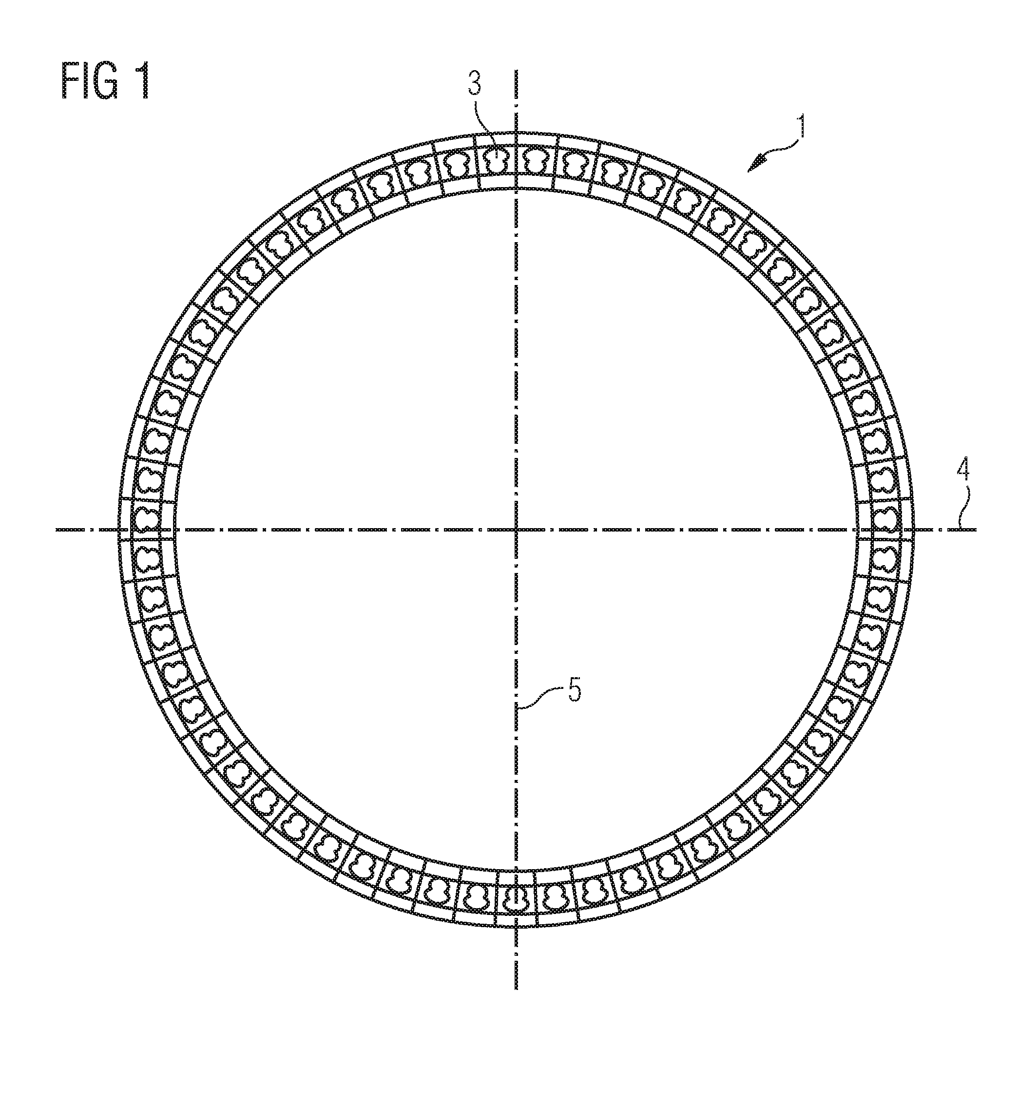
FIG. 1 schematically shows a turbine disc 1 as it is usually used in a gas turbine. The disc comprises axial grooves 3 at its periphery into which roots of turbine blades can be inserted for mounting turbine blades to the disc. Two radial symmetry axes of the turbine disc 1 are indicated by reference numerals 4 and 5.

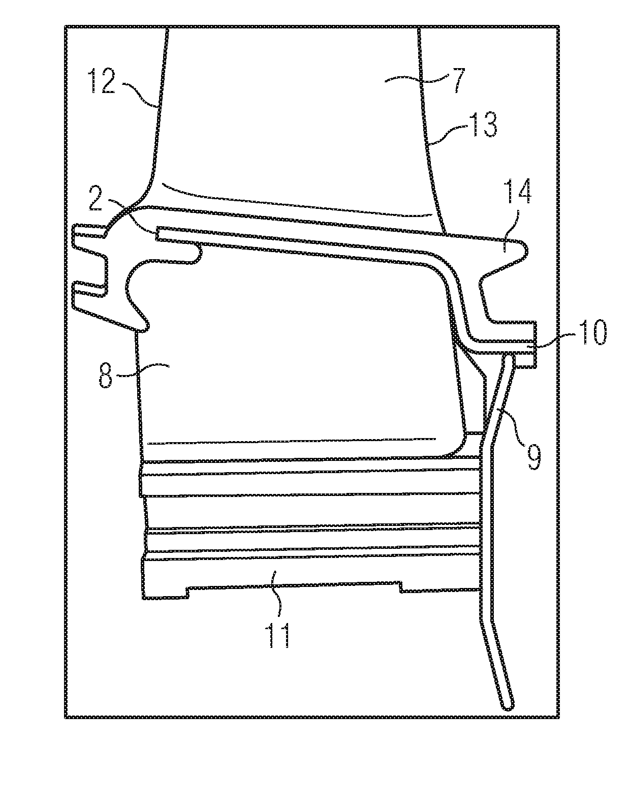
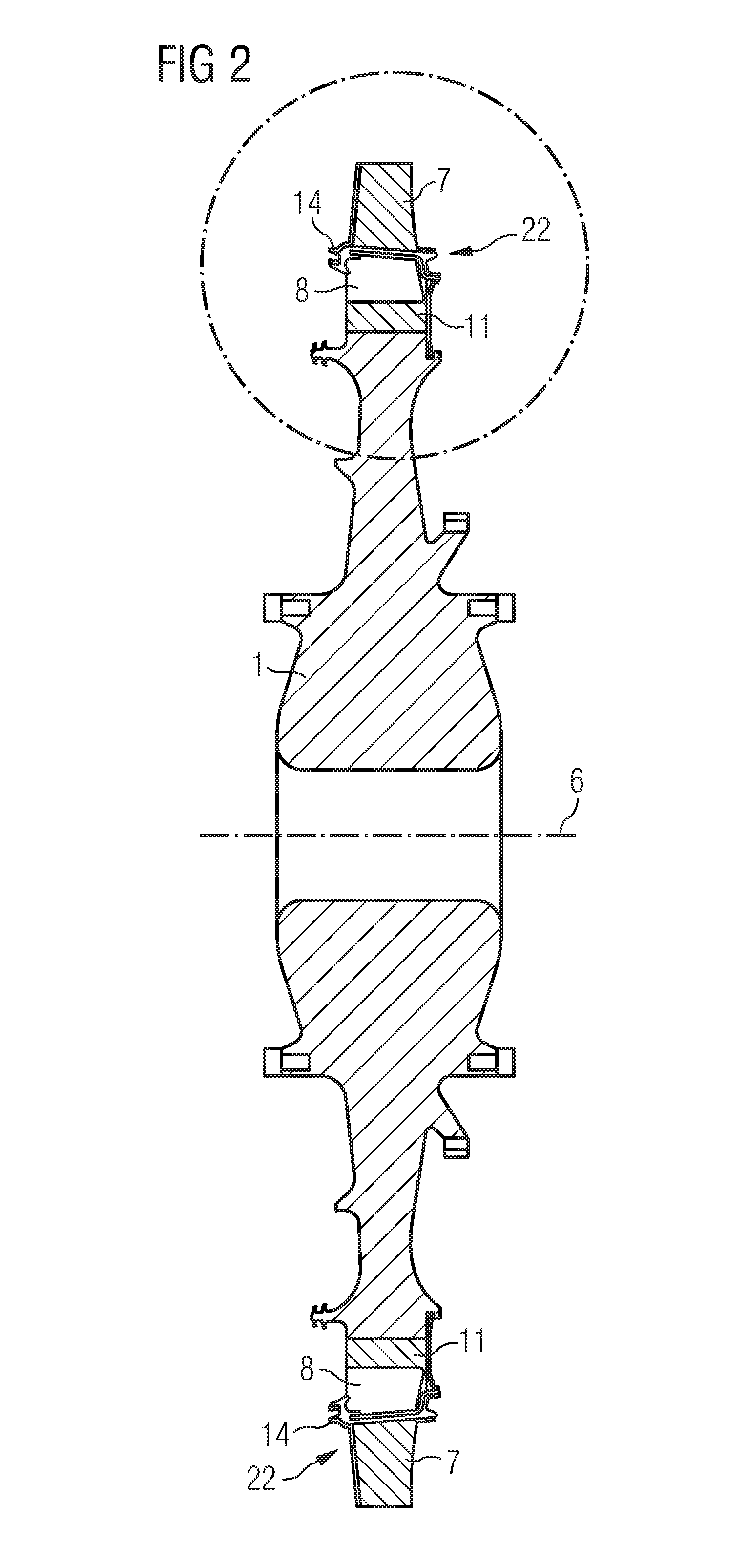
FIG. 2 schematically shows a turbine disc 1 in a sectional view along one of the symmetry axes 4 or 5. FIG. 3 shows the upper part of FIG. 2, which is indicated by a circle, in an enlarged sectional view. A portion of the turbine disc 1 with a turbine blade 22 comprising an airfoil 7, a platform 14, a blade root 11 and the root cavity 8 is shown. Furthermore, FIG. 3 shows a locking plate 9 which secures the turbine blade against slipping out of the groove of the turbine disc 1.

The turbine disc 1 is equipped with turbine blades 22. Each turbine blade 22 comprises an airfoil 7, a blade root and a platform 14. The platform 14 is located between the airfoil 7 and the blade ...


PUM


Abstract

A turbine blade assembly, in particular for a gas turbine, is provided. The turbine blade assembly includes a disc with a rotation axis, turbine blades, each turbine blade including an airfoil, a blade root and a platform between the airfoil and the blade root by which it may be fixed to the disc, locking plates and bent seal strips. The turbine blades are arranged adjacent to each other on the disc, such that gaps are present between the platforms of adjacent turbine blades and root cavities are present between the portions of the roots of adjacent turbine blades. The turbine blades are secured axially to the disc by the locking plates. The seal strips are arranged in the gaps between the platforms of neighbouring turbine blades to seal the gap and protrude axially over the blade root and over the locking plate.

Description

FIELD OF INVENTIONThe present invention relates to a turbine blade assembly, in particular for a gas turbine. The present invention further relates to a seal strip, in particular for use in a gas turbine blade assembly.BACKGROUND OF INVENTIONThe rotor of a turbine, especially of a gas turbine, can be built up from a number of discs. Each disc typically comprises a number of turbine blades which are attached to the periphery of the disc. A gas turbine blade usually comprises an airfoil, a blade root and a platform between the airfoil and the blade root. Between adjacent turbine blades which are secured to a rotor disc a root cavity occurs between root segments and platform segments.To prevent the ingress of hot gases into the root cavity formed between neighbouring blade roots which can cause undesired heating of the disc rim, blade cooling air supply and seal strips are assembled between adjacent turbine blades. These seal strips are usually simple single plane elements and are reta...

Claims


Application Information

Patent Timeline
Patent Type & Authority Applications(United States)
IPC IPC(8): F01D5/32F01D11/00
CPCF01D11/006F05D2250/70F16J15/0887
Inventor LAKE, PETERWEBB, RENE JAMES
Owner SIEMENS AG
Why Eureka
Try Eureka