Flow-Volume Regulator

Active Publication Date: 2011-01-27
NEOPERL
View PDF16 Cites 8 Cited by
  • Summary
  • Abstract
  • Description
  • Claims
  • Application Information

AI Technical Summary

Benefits of technology

[0028]In this context it is especially advantageous if the flow rate regulator has on its outer circumference at least one peripheral sealing lip which seals between the flow rate regulator and a regulator receptacle in the fluid line. As a result of this sealing lip, extending on the outer circumference of the flow rate regulator, undesired creeping currents are avoided; and an effective seal of the flow rate regulator is achieved in the area of its installation seat. In addition, the peripheral sealing lip secures the flow rate regulator, which is constructed as an insert component, and makes it easier to compress it in the fluid line.
[0029]In order to further enhance the sealing effect and/or the retai

Problems solved by technology

Since, however, the pressure losses caused, on the one hand, by the flow rate regulator and, on the other hand, by the downstream jet regulator, may add up in such a way that the downstream jet regulator does not have an adequate amount of water, the upstream flow rate regulator can also have a negative impact on the function of the downstream jet regulator—especially in the case of low pressure conditions.
Therefore, in such areas, where, as a rule, only low water pressure prevails, a flow rate regulator can have such a negative impact on the available volume of water, that it is not practical to install such flow rate regulators in such areas.
This drawback may be further intensified, i

Method used


Image

  • Flow-Volume Regulator
  • Flow-Volume Regulator
  • Flow-Volume Regulator

Examples


Embodiment Construction

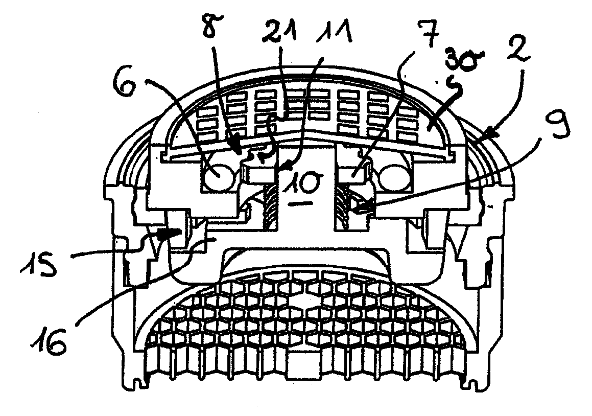
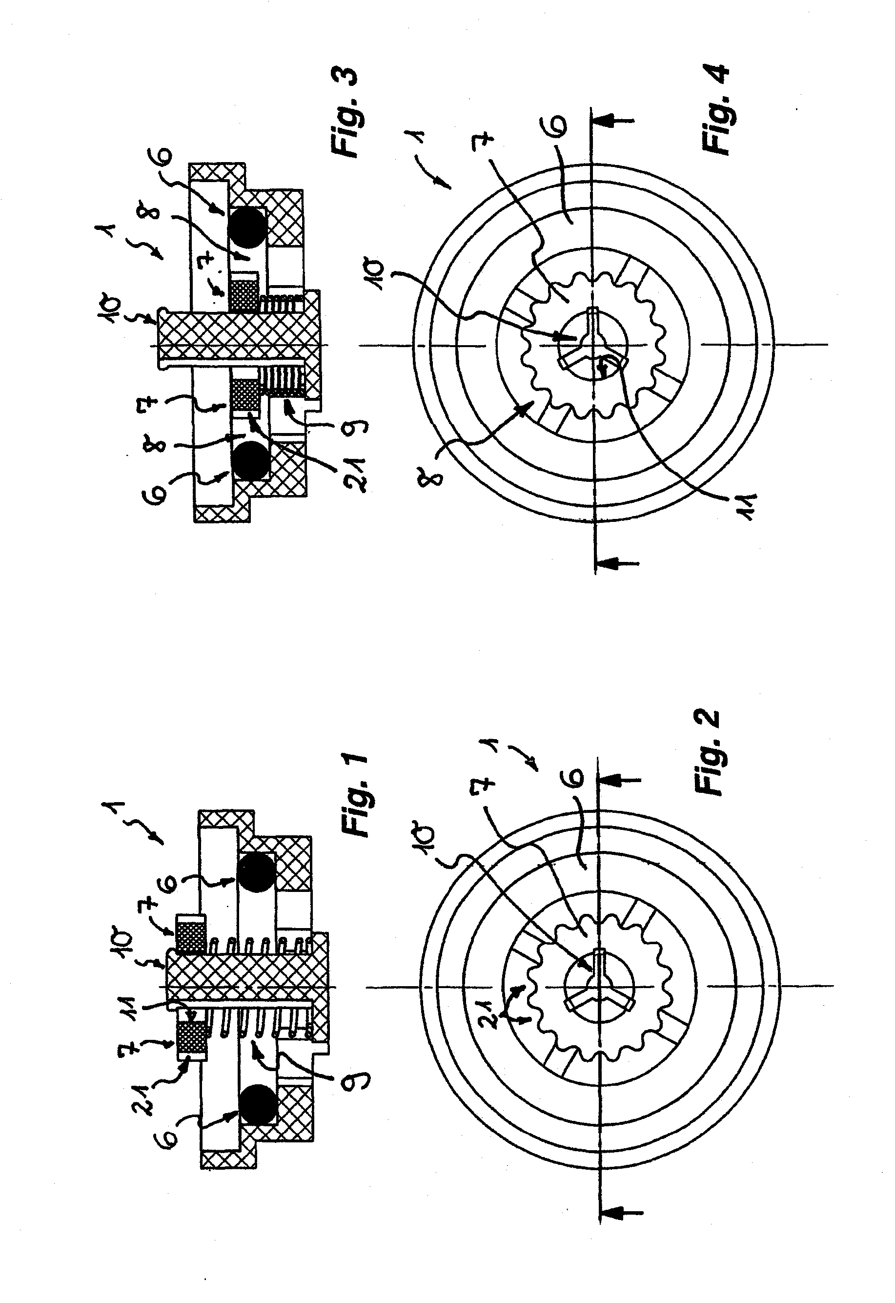
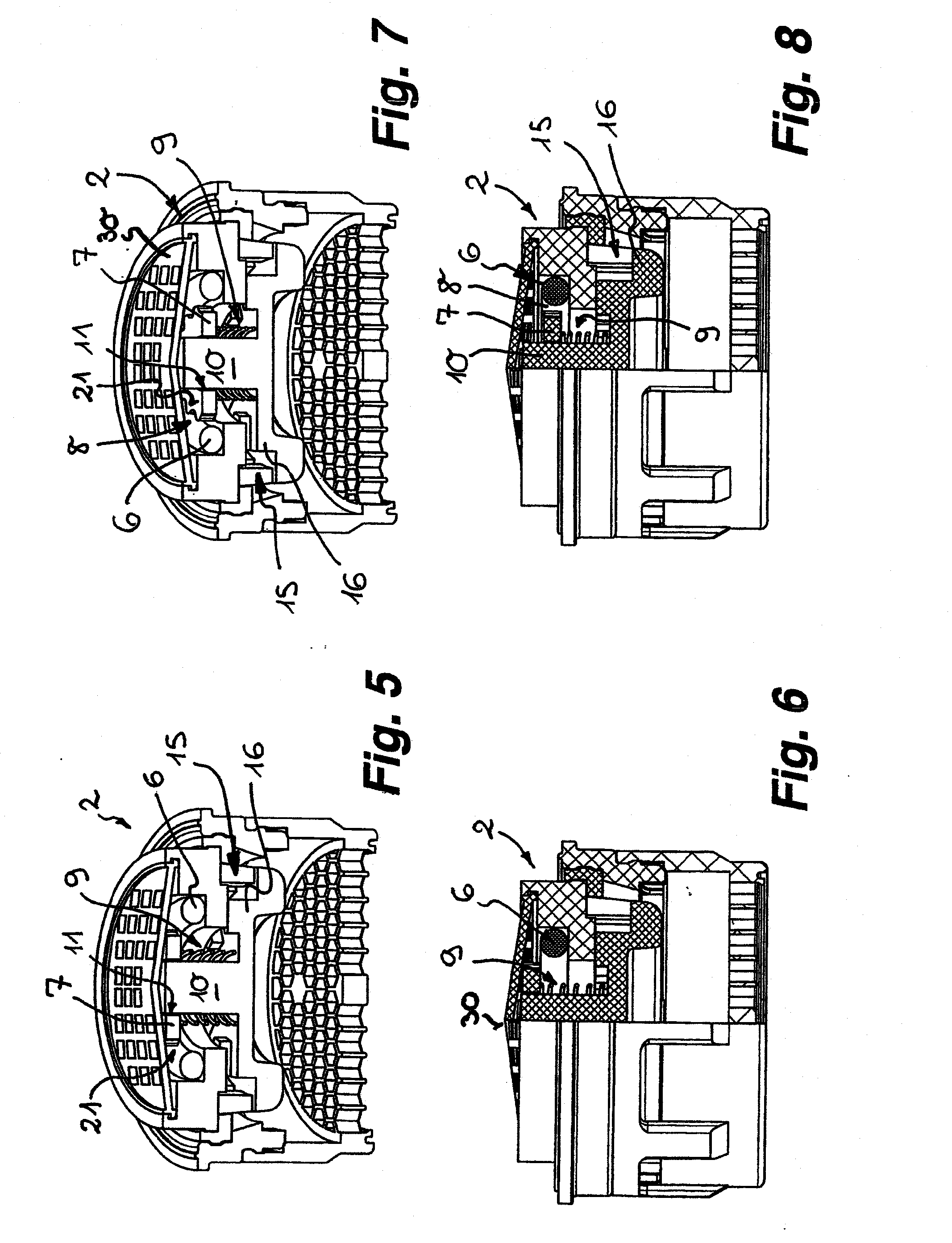
[0050]FIGS. 1 to 24 and 28 to 31 depict a flow rate regulator in embodiments designated by reference numerals 1, 2, 3, 4, 5, 20 and 40, which are designed to equalize the maximum flow rate of a fluid per unit of time that flows through a line or preferably flows out of a line, and to set it to a predetermined value. The flow rate regulators 1, 2, 3, 4, 5, 20 and 40 depicted here are components of a sanitary installation unit, which can be inserted, for example, into an outlet orifice (not depicted here in detail) and which can be mounted in this way on the water spout of a plumbing outlet fixture.

[0051]The flow rate regulators 1, 2, 3, 4, 5, 20 and 40 include an annular restrictor 6, which is made of an elastic material and which, in the functional position shown in the FIGS. 3, 4; 7, 8; 11, 12; 15, 16; 19, 20; 21, 22 and 30, 31, delimits a control gap 8 between itself and an internally and / or externally disposed regulating profile 21. The control gap 8 is variable in its unrestrict...


PUM


Abstract

A fluid flow regulator includes a regulating profile which is either centrally or peripherally disposed within the flow rate regulator, and an annular restrictor which is made of an elastic material. In a functional position of the flow rate regulator, the restrictor delimits a control gap between itself and the regulating profile. In a starting position of the flow rate regulator, the flow rate regulator has an unrestricted flow cross section that is larger than the control gap. The unrestricted flow cross section of the flow rate regulator is variable by a deformation of the restrictor in response to a pressure differential that is generated when a fluid flows through the flow rate regulator. The relative position of the restrictor and the regulatory profile is variable, and moveable against a reset force, into the functional position from the starting position, in response to a flow of fluid within the flow rate regulator. The reset force may be provided in the form of a spring.

Description

[0001]This application is a national stage of PCT International Application No. PCT / EP2007 / 010105, filed Nov. 22, 2007, which claims priority under 35 U.S.C. §119 to German Patent Application No. 10 2006 057 787.6, filed Dec. 6, 2007, the entire disclosure of which is herein expressly incorporated by reference.[0002]The invention relates to a flow rate regulator with an annular restrictor that is made of an elastic material and delimits a control gap between itself and an internal and / or external lying regulating profile in a functional position. The unrestricted flow cross section of the control gap is variable by the restrictor, which deforms under the pressure differential that is generated when the fluid flows through.BACKGROUND OF THE INVENTION[0003]Flow rate regulators already exist in a variety of designs. With the aid of such flow rate regulators the maximum flow rate of a fluid per unit of time is supposed to be equalized independently of the potential pressure fluctuations...

Claims


Application Information

Patent Timeline
IPC IPC(8): F16K31/12
CPCG05D7/012G05D7/0133Y10T137/7791Y10T137/7792
Inventor ZOLLER, UWE
Owner NEOPERL
Why Eureka
Try Eureka